Auto-correcting bow sight

a bow sight and auto-correction technology, applied in the field of bow sighting devices, can solve the problems of wasting shot opportunities, laser-based range finders taking time to calculate the desired distance, and accurate range estimation for archers

Active Publication Date: 2010-05-13
WISCONSIN ARCHERY PROD
View PDF38 Cites 46 Cited by
  • Summary
  • Abstract
  • Description
  • Claims
  • Application Information

AI Technical Summary

Benefits of technology

[0013]In accordance with one aspect of the invention, a bow sight is provided that allows an archer to take “dead aim” or aim directly at a target, at all times, by illuminating or otherwise displaying an aim indicator(s) that is positioned so as to compensate for situation-specific shooting and environmental factors that influence arrow flight. This can be all done while the bow is at full draw and ready for the shot.
[0014]In accordance with another aspect of the invention, a bow sight is provided that automatically corrects and compensates for various dynamically changing aiming, shooting, and / or environmental conditions. The bow sight can include various integrated sensors or other sensing-type devices, such as a range finder, an inclinometer, and an anemometer, which communicate with a processor or other control device. The processor, based on, e.g., signals from the sensors, may illuminate one or more aim indicators provided within a sight array which includes multiple aim indicators. In this configuration, a default sighted-in position can be preliminarily established and designated by a first aim indicator provided within the sight array. Then, during use, the system can correct and compensate for factors such as distance, shot angle and windage settings. In so doing, effects of environmental and use influences can be mitigated by changing a discrete position of the aim indicator within the sight array based on, e.g., shooting angle, wind direction, wind velocity, shot distance or other factors.
[0016]In yet another aspect, once installed on a bow and preliminarily sighted in, the bow sight can be entirely self-reliant and dynamically re-sighted in, or aim-corrected on a per-shot basis, based on the particular use or environmental conditions at a particular point in time. Changes can be made to the bow dynamics or the arrow choice and can be easily inputted or sighted in at a practice range to accommodate such changes.

Problems solved by technology

Accurately estimating range can prove difficult for archers, especially in, e.g., an actual hunt with game animals that are amongst obstacles and / or moving so that an actual shooting distance varies over time.
Compounding this difficulty is that from a tree stand not only the distance changes but so does the shooting angle both of which need to be quickly estimated along with their effects on pin selection.
However, such laser-based range finders take time to calculate the desired distance.
Furthermore, such laser-based range finders are handheld or stand-alone units requiring archers to use their hands to manipulate, preventing them from grasping their bows in a shooting alert manner and determine a target distance simultaneously, whereby they cannot draw the bow and utilize the range finder at the same time.
At times, the game animal does not stay still long enough for the archer to draw and release an arrow after finding the range to the animal, whereby the shot opportunity is lost due to the time required for shot preparation.
Such pendulum-type sights require moving components that can be damaged, misaligned, or otherwise harmed by brush or other obstacles while traversing a field, woods, or other habitat on the way to one's hunting stand, and the pendulum-type sight may not compensate for all angles, elevations, and distances.
Such handheld or stand-alone anemometers suffer the same drawbacks as discussed above with respect to the laser-based range finders.

Method used


Image

  • Auto-correcting bow sight
  • Auto-correcting bow sight
  • Auto-correcting bow sight

Examples


Embodiment Construction

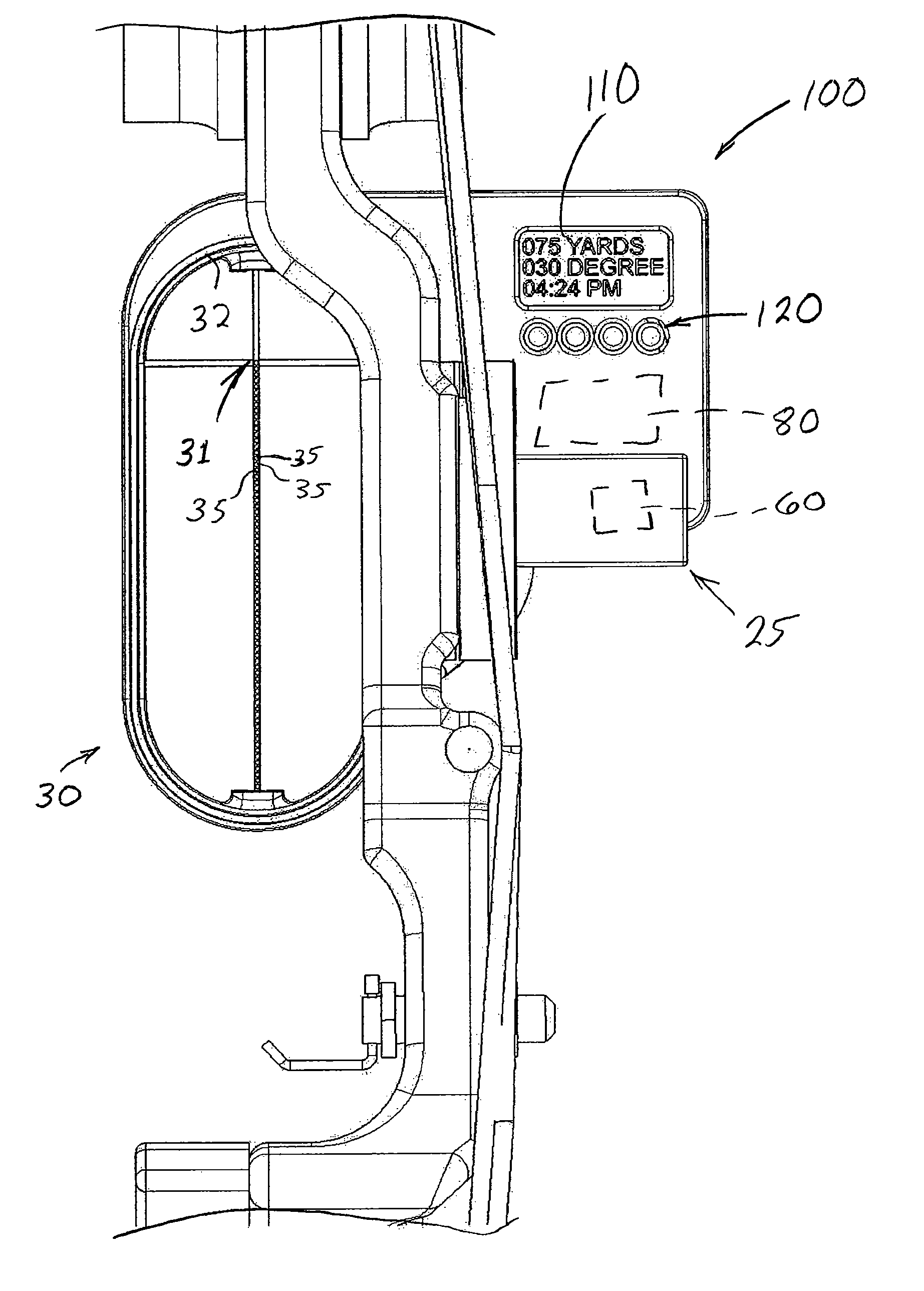
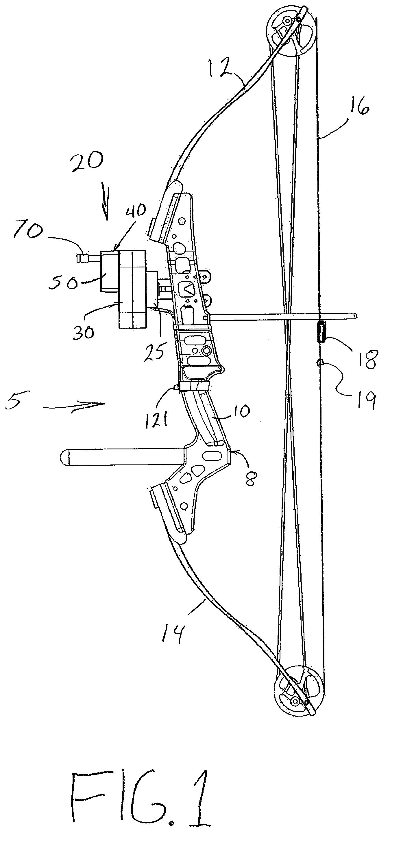
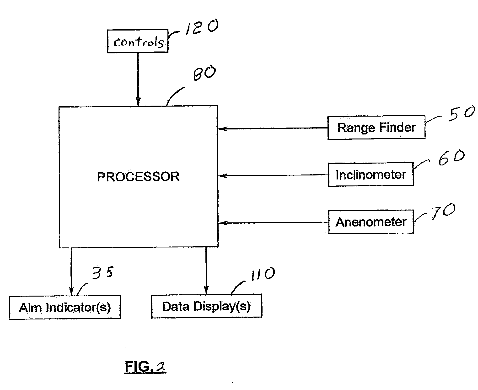
[0040]As discussed in the “Summary” section above, the invention relates to a bow sight that compensates for situation-specific shooting and environmental factors that can influence arrow flight, for example, by performing a situation-specific aim evaluation and correction procedure. The preferred bow sight has selectively illuminating or displayable aim indicators that are illuminated or otherwise visually or audibly displayed at positions which compensate for such situation-specific shooting and environmental factors in a manner that allows an archer to take “dead aim” with, or aim directly at, an intended target at all times.

[0041]Various embodiments of a bow sight will now be described that achieve these and many other goals, it being understood that other configurations may be provided that fall within the scope of the present invention. Such exemplary embodiments of the bow hunting accessory device of the present invention are illustrated in the accompanying drawings in which ...


PUM


Abstract

A bow sight automatically corrects and compensates for various dynamically changing aiming, shooting, and / or environmental conditions. The bow sight can perform situation-specific aim evaluations and corrections to correct or compensate for situation-specific shooting and environmental factors, at a given time and on a per-shot basis. The bow sight includes integrated sensor-type devices, such as a range finder, an inclinometer, and an anemometer, which detects values of situation-specific shooting and environmental factors and communicates such detected values with a processor or other control device. The processor uses the situational specific data, as well as bow and arrow performance data, and data from shot calibrations, to calculate precise vertical and horizontal aim compensations required to accurately hit the desired target point. The bow sight displays a new crosshair, dot, or multiple dot set, to direct the archer to a situation-specific aiming point for the most accurate shot under those particular circumstances.

Description

CROSS-REFERENCE TO RELATED APPLICATIONS[0001]This application claims priority under 35 U.S.C. §119 from U.S. Provisional Patent Application Ser. No. 61 / 112,835, filed on Nov. 10, 2008 and entitled “AUTO-CORRECTING BOW SIGHT,” which is herein expressly incorporated by reference in its entirety, for all purposes.BACKGROUND OF THE INVENTION[0002]1. Field of the Invention[0003]The invention relates generally to hunting accessories and, more particularly, to devices for bow sighting devices for establishing aiming positions while using a bow.[0004]2. Discussion of the Related Art[0005]Archery sports are growing in popularity and include, e.g., hunting, conventional target shooting, 3-D target shooting, electronic video mock hunting, and other activities. Archery technology has progressed over time, with some of the most notable technological advancements occurring within the last few decades. Notable examples of such advancements include the development of (i) compound bows that allow an...

Claims


Application Information

Patent Timeline
Patent Type & Authority Applications(United States)
IPC IPC(8): F41G1/467G01C3/00G06F19/00
CPCF41G1/467
Inventor GORSUCH, TIMOTHY M.BUCKLEY, JAMES A.
Owner WISCONSIN ARCHERY PROD
Why Eureka
Try Eureka