Method and system of subduct & cable installation

A technology of sub-pipes and pipes, applied in the field of installation of components and sub-pipes in the main pipe, to achieve the effect of reducing the cross-sectional area and volume

Inactive Publication Date: 2005-08-24
BRITISH TELECOMM PLC
View PDF0 Cites 1 Cited by
  • Summary
  • Abstract
  • Description
  • Claims
  • Application Information

AI Technical Summary

Problems solved by technology

[0004] The present invention aims to solve or substantially improve and overcome the above-mentioned problems

Method used


Image

  • Method and system of subduct & cable installation
  • Method and system of subduct & cable installation
  • Method and system of subduct & cable installation

Examples


Embodiment Construction

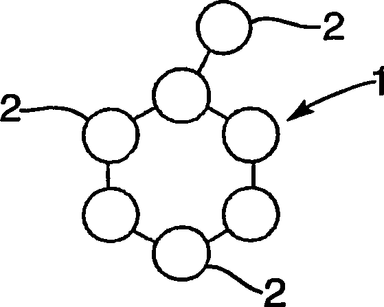
[0033] figure 1 The sub-pipes shown comprise a multiple sub-pipe 1 of the present invention comprising a plurality of sub-pipes 2 connected together along their lengths. figure 1 The sub-duct 2 shown in FIG. 2 is in an expanded state and is in an inverted (inside-out) state, and the inner surface in the normal state becomes the outer surface in this state. In the preferred embodiment, the multiple subducts are manufactured in this inverted (inside out) state.

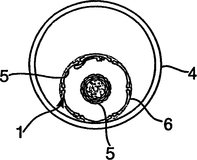
[0034] figure 2 The multiple sub-duct 1 is shown in a non-expanded state and during installation in the main duct 4 . Part of the sub-pipeline 1 in the overturned state is overturned into the main pipeline 4 . When the sub-pipe 1 is installed, it is turned inside out so that the outer surface in this state (ie the inner surface 5 in the normal state) becomes the inner surface, and the outer surface 6 in the normal state becomes the outer surface. This process will be described in detail below.
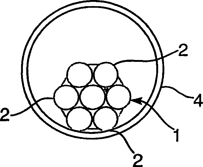
[0035] image 3 S...


PUM


Abstract

A method and system of installing a cable into a duct, comprising increasing the cross-sectional areas of subducting provided in the duct, so as to allow the cable to be received into the subducting, and then decreasing the cross-sectional area of the subducting containing the cable so as to reduce the volume occupied by the subducting in the duct. Cables may be inserted into the subducting, for example, by forcing compressed gas through the subducting, which simultaneously inflates the subducting.

Description

technical field [0001] The invention relates to the installation of components and sub-pipes in main pipes. In particular, the present invention relates to a method and a system for installing components in a duct, to a method and a system for installing a sub-duct in a main duct, and to a sub-duct in which cables are inserted. Background technique [0002] For telecommunications companies, for example, there is often a need to install cables into long ducts that are part of a large installed duct network. Due to the presence of installed cables, many such ducts leave only limited space for the remaining cables, making the installation process difficult. Installation costs are inherently high, making installation space a potentially valuable asset. This is the case for partially filled pipes as well as for empty pipes. [0003] Typical installation procedures involve the use of compressed gas that is forced into the pipe to create a viscous flow along the pipe, which crea...

Claims


Application Information

Patent Timeline
Patent Type & Authority Applications(China)
IPC IPC(8): G02B6/46G02B6/44H02G1/06H02G1/08
CPCH02G1/08H02G1/086Y10T29/53348Y10T29/49805Y10T29/49911Y10T29/49838G02B6/44
Inventor 菲利普·阿尔佛雷德·巴伯克里斯多佛·菲斯克安德鲁·约翰·梅休西蒙·伊万·费希尔
Owner BRITISH TELECOMM PLC
Why Eureka
Try Eureka