Autonomous device for the magnetic handling of an electronic component

A technology for processing equipment and autonomous equipment, applied in the direction of electrical components, electrical components, etc.

Inactive Publication Date: 2005-08-24
WAVECOM SA
View PDF1 Cites 2 Cited by
  • Summary
  • Abstract
  • Description
  • Claims
  • Application Information

AI Technical Summary

Problems solved by technology

And this manual intervention cannot be considered for the reasons mentioned above involving electronic components or macro components

Method used


Image

  • Autonomous device for the magnetic handling of an electronic component
  • Autonomous device for the magnetic handling of an electronic component
  • Autonomous device for the magnetic handling of an electronic component

Examples


Embodiment Construction

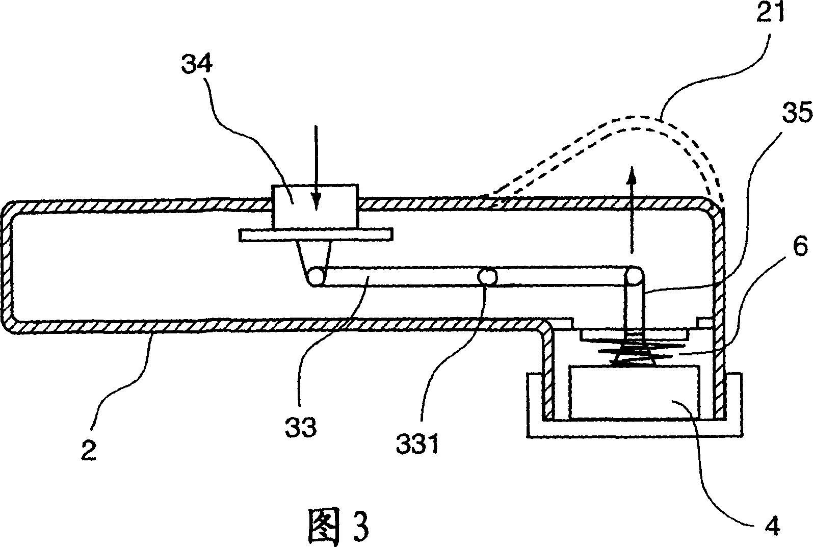
[0067] The present invention therefore relates to an autonomous device for processing elements, realizing permanent magnets, and a mechanical device that allows the magnets and elements to be separated with high precision without any manual contact with the latter.

[0068] Figures 1 and 2 show an example of such a device in grip and release positions, respectively.

[0069] The autonomous device for processing the electronic component 1 includes a main body 2 and a gripping head 3 that are combined with each other.

[0070] In Figures 1 and 2, we notice that the main body 2 and the gripping head form an angled single unit, for example, composed of two separate plastic half-shells combined with each other. However, according to another possible embodiment, the head can be rotatably mounted on the device body.

[0071] It is also conceivable that the main body and the gripping head extend in an axial manner.

[0072] We also note that according to another way that can be conceived ...


PUM


Abstract

The invention relates to an autonomous device that is used to handle an electronic component (1), comprising a body (2) and a head (3) for picking up said component (1) magnetically. Moreover, the aforementioned pick-up head (3) comprises a permanent magnet (4) and mechanical separation means which can move in relation to one another such that the device can occupy at least two positions, namely: a pick-up position, in which the magnet (4) interacts with the component (1) so as to keep said component in contact with a contact surface of the head (3); and a release position, in which the magnet (4) is moved away from the component (1) such as to stop the magnetic interaction.

Description

Technical field [0001] The present invention relates to the technical field of processing electronic components, particularly for the purpose of assembling and replacing the electronic components on a printed circuit board. More precisely, the present invention relates to a tool with a chuck that allows such elements to be grasped and moved. Background technique [0002] The present invention can be applied in various fields, such as telecommunication, wireless data transmission, automobile, electronic technology, embedded electronic technology, electronic component transmission industry, chemical industry, laboratory and medical department. [0003] The wording "electronic components" here means every type of component that may be handled carefully and precisely, with no apparent damage during implementation. Specifically, they are components that have pins that are brazed to the printed circuit on their surface and / or surroundings. [0004] For example, they can be standard com...

Claims


Application Information

Patent Timeline
Patent Type & Authority Applications(China)
IPC IPC(8): H05K13/04
CPCH05K13/0404H05K13/0447
Inventor 亚历克西斯·德比比考夫
Owner WAVECOM SA
Why Eureka
Try Eureka