Rotary damper and console box

A technology of rotating dampers and rotating shafts, which is applied in the direction of shock absorbers, shock absorbers, liquid shock absorbers, etc., and can solve problems such as inconvenience, difficulty in adjusting braking force, troublesome operation, etc.

Inactive Publication Date: 2005-08-31
SOMIC ISHIKAWA INC
View PDF0 Cites 10 Cited by
  • Summary
  • Abstract
  • Description
  • Claims
  • Application Information

AI Technical Summary

Problems solved by technology

However, since such a rotary damper must be operated from the outside in order to adjust the generated braking force, for example, as with the inner cover of the above-mentioned console box, the amount of change in the rotational torque is not constant, and the rotational torque is frequent. It is not suitable for the control object that changes. If it is to be applied to such a control object, whenever the rotation torque changes as the object is taken out or put into the inner cover, it is necessary to predict the amount of change in the rotation torque However, it is operated from the outside to adjust the braking force of the rotary damper. In this way, in addition to adjusting the proper braking force, it is very difficult, and its operation is also very troublesome and inconvenient.

Method used


Image

  • Rotary damper and console box
  • Rotary damper and console box
  • Rotary damper and console box

Examples


Embodiment Construction

[0049] Hereinafter, embodiments of the present invention will be described in detail with reference to the drawings.

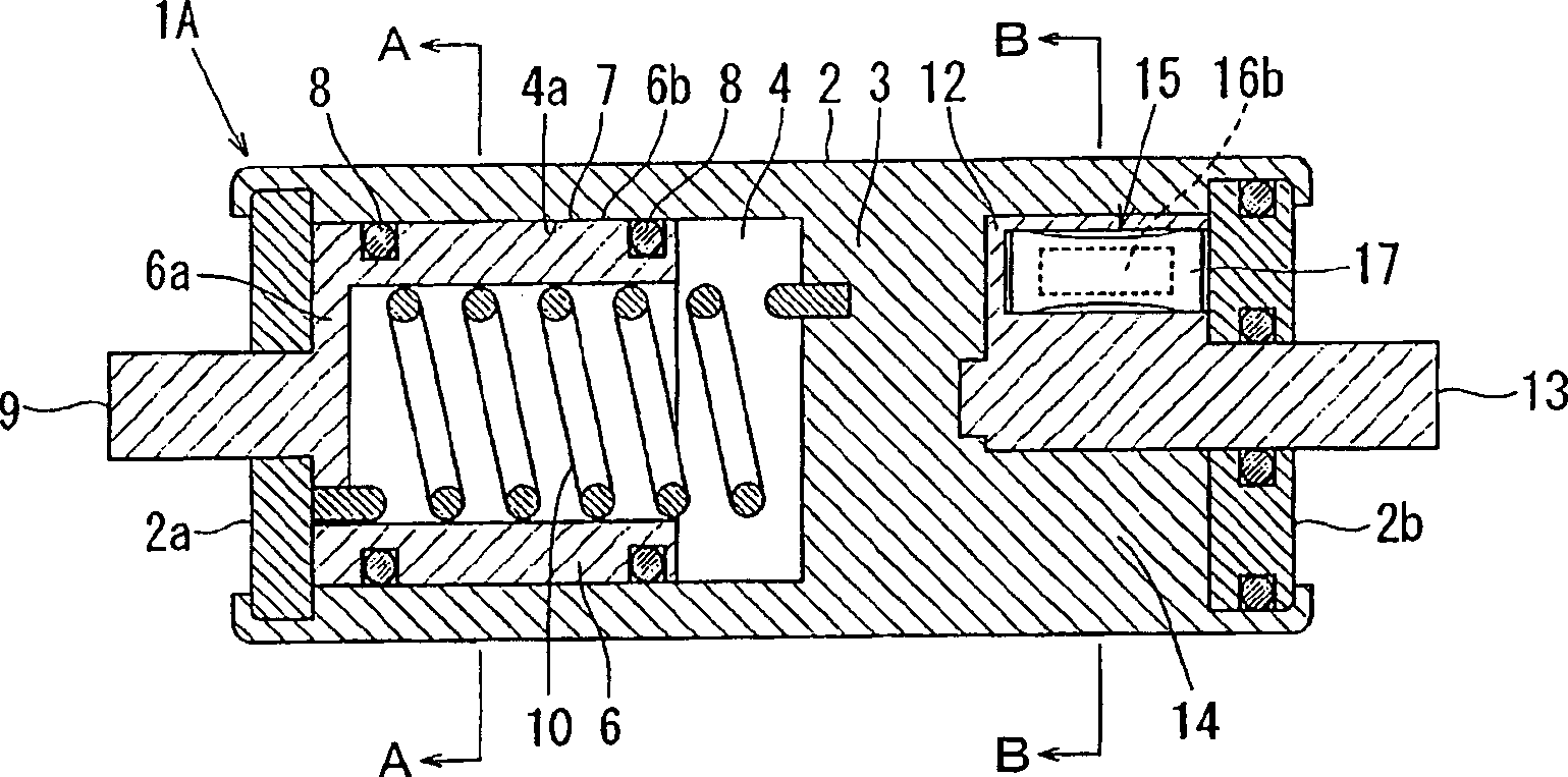
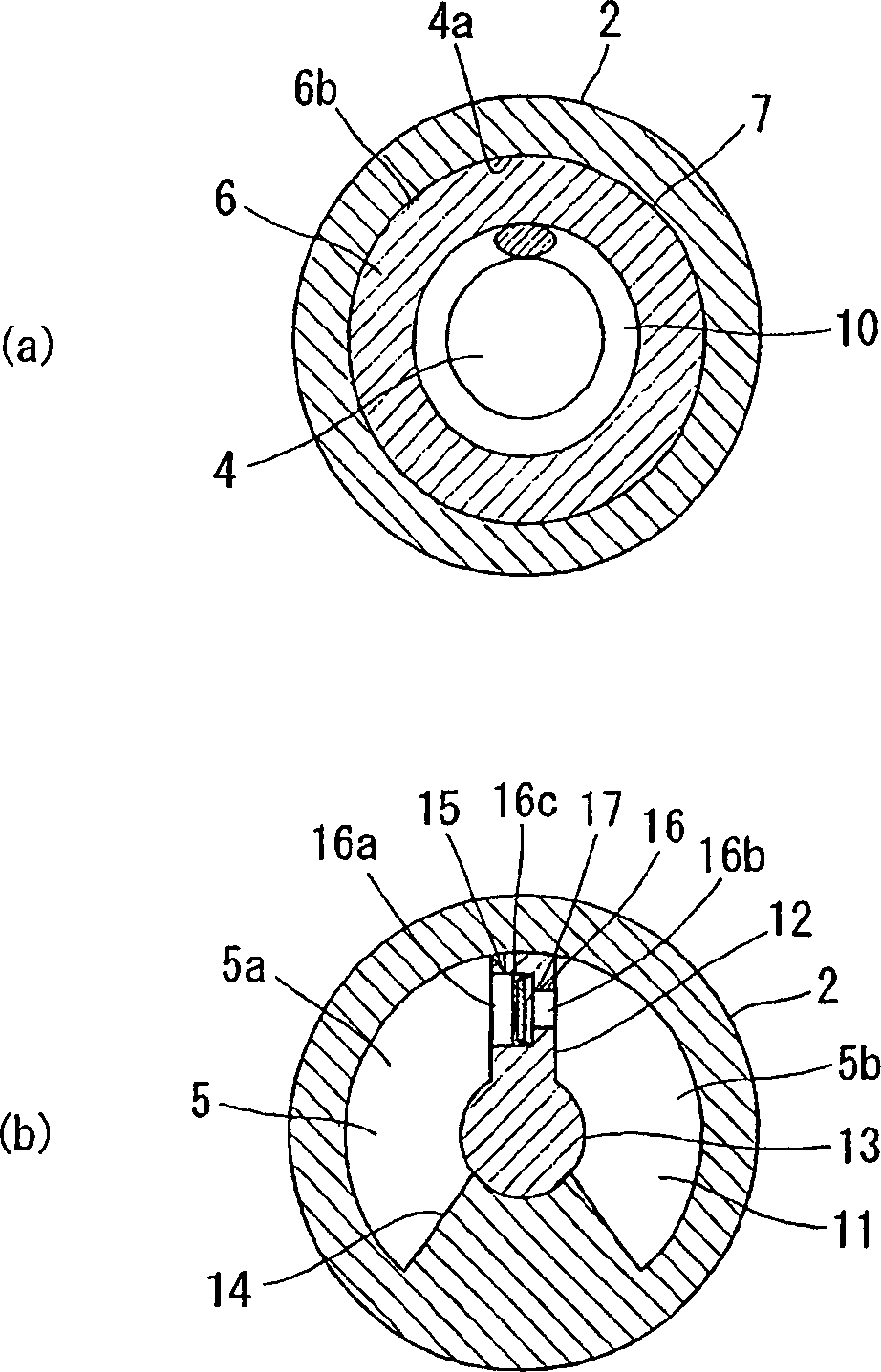
[0050] figure 1 and figure 2 It is a figure which shows the internal structure of the rotary damper related to the 1st Embodiment (hereinafter referred to as "1st Embodiment") of this invention, figure 1 is a sectional view, figure 2 (a) is figure 1 A cross-sectional view of part A-A, figure 2 (b) is figure 1 Sectional view of part B-B of . As shown above, the rotary damper 1A according to the first embodiment has the first chamber 4 and the second chamber 5 separated by the partition wall 3 provided in the main body case 2 . In the main body case 2, openings on both sides in the axial direction are closed by covers 2a and 2b, respectively.

[0051] In the first chamber 4, a rotor 6 is rotatably arranged. The rotor 6 is made into a substantially cylindrical shape with one end closed by an end wall 6a and the other end opened. However, the shape of ...


PUM


Abstract

An object of the invention is to provide a rotary damper which can individually control two controlled subjects independently rotatable with each other by utilizing both a viscous resistance by a viscous material and a resistance by a viscous fluid and putting properties thereof to good use. A rotary damper ( 1 A) is provided with first and second chambers ( 4, 5 ) which are separated by a partition wall ( 3 ), a rotor ( 6 ) which is rotatably arranged within the first chamber ( 4 ), a viscous material ( 7 ) which is filled in a slight gap between the rotor ( 6 ) and a slidable contact surface slidably contacted with the rotor ( 6 ), a viscous fluid ( 11 ) which is filled in the second chamber ( 5 ), and a vane ( 12 ) which is swingably arranged within the second chamber ( 5 ) filled with the viscous fluid ( 11 ).

Description

technical field [0001] The present invention relates to a rotary damper and a console box including the rotary damper. Background technique [0002] Conventionally, as a rotary damper, a type in which a braking force is generated by viscous resistance of a viscous body filled in a small gap between a rotor and a sliding contact surface in sliding contact with the rotor is known (hereinafter referred to simply as "Rotary damper that utilizes viscous resistance."), and a type that generates braking force from the resistance of viscous fluid pushed by the blade (hereinafter referred to as "rotary damper that utilizes resistance of viscous fluid."), generally , any type of rotary damper, are manufactured as separate products. [0003] In addition, since the rotary damper using viscous resistance and the rotary damper using viscous fluid resistance have different braking characteristics, it is usually suitable to be used separately according to the difference in the control obje...

Claims


Application Information

Patent Timeline
Patent Type & Authority Applications(China)
IPC IPC(8): B60R7/04F16F9/12F16F9/14
CPCF16F9/145B60R7/04F16F9/12
Inventor 菅野秀则志村良太板垣正典
Owner SOMIC ISHIKAWA INC
Why Eureka
Try Eureka