Input/output interface for computer aided diagnosis (CAD) system

A computer-aided, output interface technology, used in computer-aided medical procedures, computer parts, computing, etc.

Inactive Publication Date: 2005-09-07
RIVERAIN MEDICAL GROUP
View PDF1 Cites 6 Cited by
  • Summary
  • Abstract
  • Description
  • Claims
  • Application Information

AI Technical Summary

Problems solved by technology

However, in addition to the above-mentioned capabilities, there...

Method used


Image

  • Input/output interface for computer aided diagnosis (CAD) system
  • Input/output interface for computer aided diagnosis (CAD) system
  • Input/output interface for computer aided diagnosis (CAD) system

Examples


Embodiment Construction

[0026] In this specification, a chest X-ray based CAD system is used as an example. However, the present invention is not limited to this system, but is applicable to general CAD systems. Furthermore, the embodiments described herein refer to a single processing unit connected to one or more image acquisition devices; however, the invention can also be used in configurations consisting of multiple processing units.

[0027] The present invention includes methods and systems that provide an interface to a CAD system. Such interfaces include both input and output interfaces.

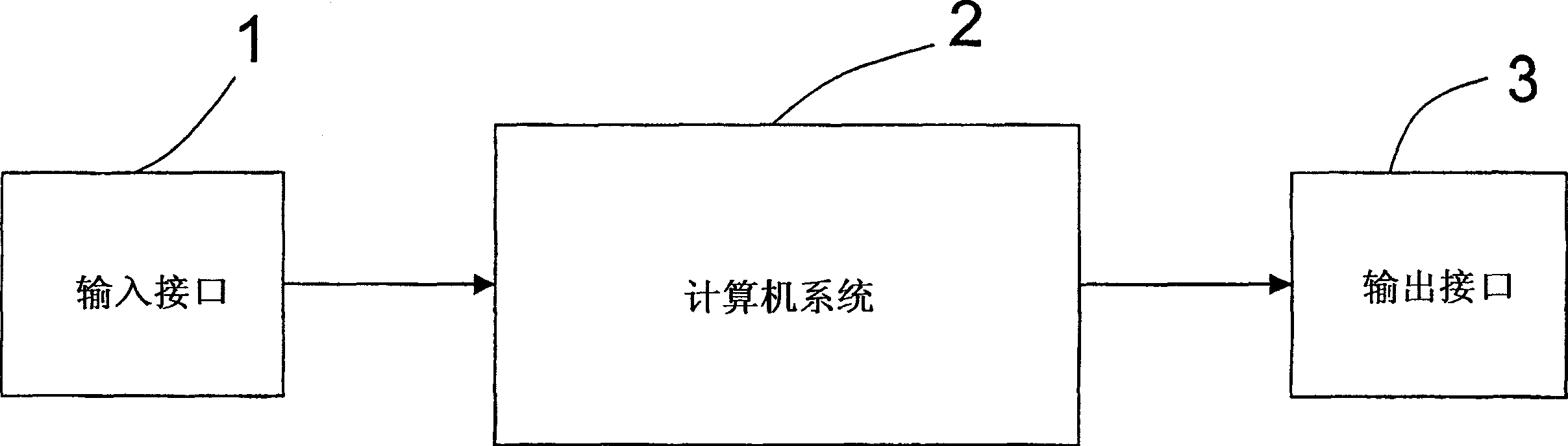
[0028] attached figure 1 Shown is a block diagram of a typical CAD system. The heart of such a system is a computer system 2 running software implementing CAD functions. Data from users and / or other systems is input into computer system 2 via input interface 1 . Computer system 2 provides output via output interface 3 . Although the input interface 1 and the output interface 3 are shown as separate b...


PUM


Abstract

A user interface (3) for facilitating a computer-aided diagnosis (CAD) includes an image input device (12) that receives and scans the multiple images, and a film feeder (14) transports films from a film developer (15) to the scanner.(12). A multi-image identification input device uses bar code reading, numeric keypad, keyboard, network, and/or mouse to enter multiple image identification prior to image scanning. A display includes an image identification area, case processing status area, and a CAD detection and user modification area. The user can edit CAD results such as accept and remove, and can add new diagnosis results to create a new composite diagnosis result.

Description

field of invention [0001] The present invention relates to methods and systems for computer-aided diagnosis (CAD) and digital processing of abnormalities in radiological images. More specifically, the present invention relates to an automated method and system user interface for re-screening and detection of anomalies. Background technique [0002] Computer-aided diagnostic (CAD) systems use digital processing methods to assist users in the identification of abnormalities. US Patent No. 5,917,929 describes a user interface that facilitates film input into a CAD system. The user interface includes a scanner that receives and scans film-based images and a film feeder that holds the films and feeds them to the scanner. A touch-sensitive display is provided to display status information to and receive instructions from the operator. The display screen displays a miniature image of the film with color-coded borders that indicate to the operator the stage of processing of the f...

Claims


Application Information

Patent Timeline
IPC IPC(8): G16H30/20G16H40/63G16H50/20G16Z99/00
CPCG06F19/3487G06F19/3406G06F19/321G16H40/63G16H15/00G16H50/20G16H30/20G16Z99/00
Inventor 弗莱明·Y·卢尔张荣峰林至贤徐昕炜H·迈克尔·耶
Owner RIVERAIN MEDICAL GROUP
Why Eureka
Try Eureka