Multi-Image Deblurring

a multi-image, deconvolution technology, applied in the field of image processing, can solve problems such as ill-posed deconvolution

Active Publication Date: 2010-09-30
MITSUBISHI ELECTRIC RES LAB INC
View PDF11 Cites 42 Cited by
  • Summary
  • Abstract
  • Description
  • Claims
  • Application Information

AI Technical Summary

Benefits of technology

[0014]Blurred images exhibit nulls (zeros) in the frequency transform of the PSF, leading to an ill-posed deconvolution. Hardware solutions to avoid this problem require specialized devices such as a coded exposure camera or an accelerating sensor motion. We use conventional video cameras and introduce the...

Problems solved by technology

Blurred images exhibit nulls (zeros) in the frequency ...

Method used


Image

  • Multi-Image Deblurring
  • Multi-Image Deblurring
  • Multi-Image Deblurring

Examples


Embodiment Construction

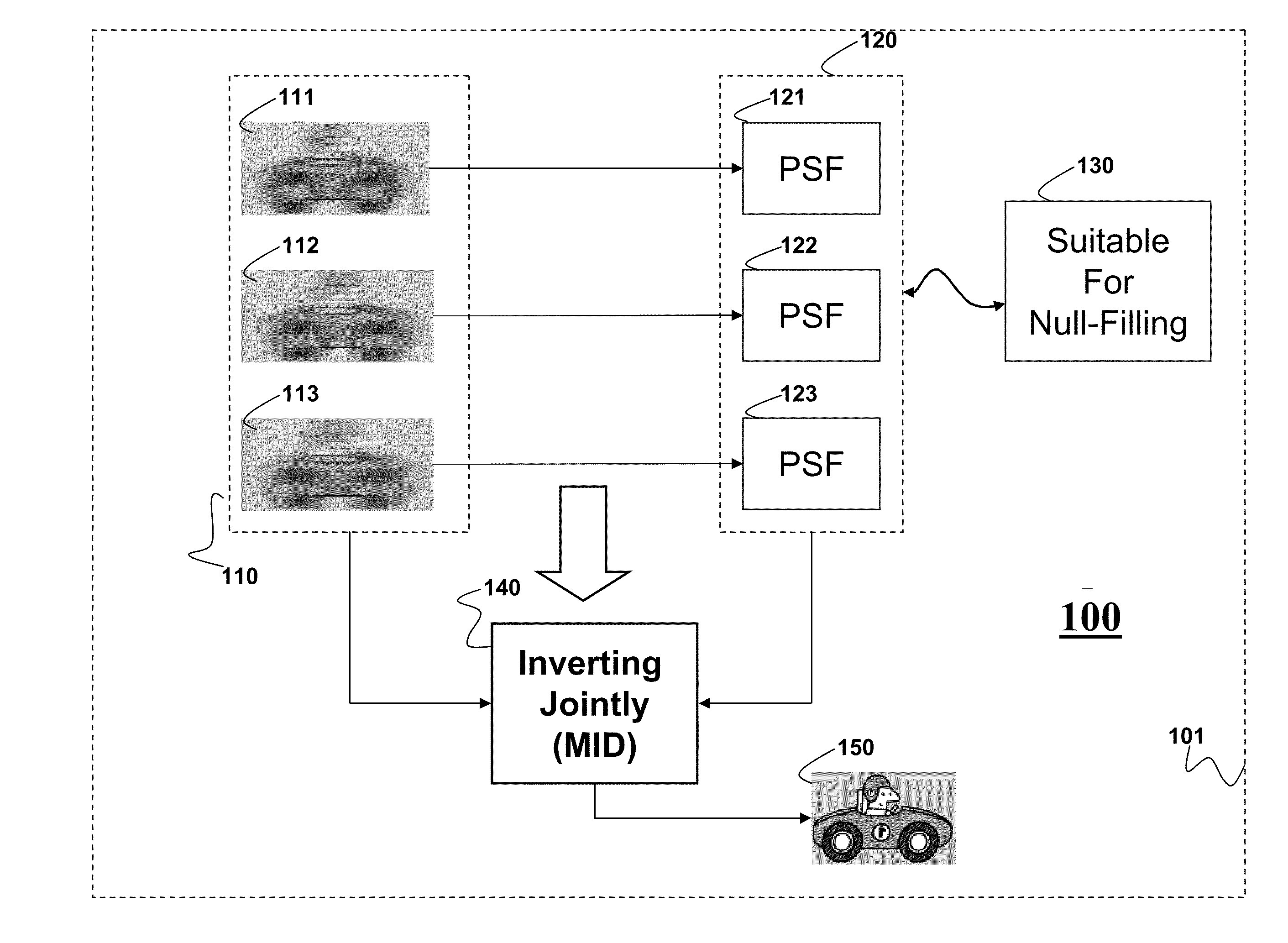
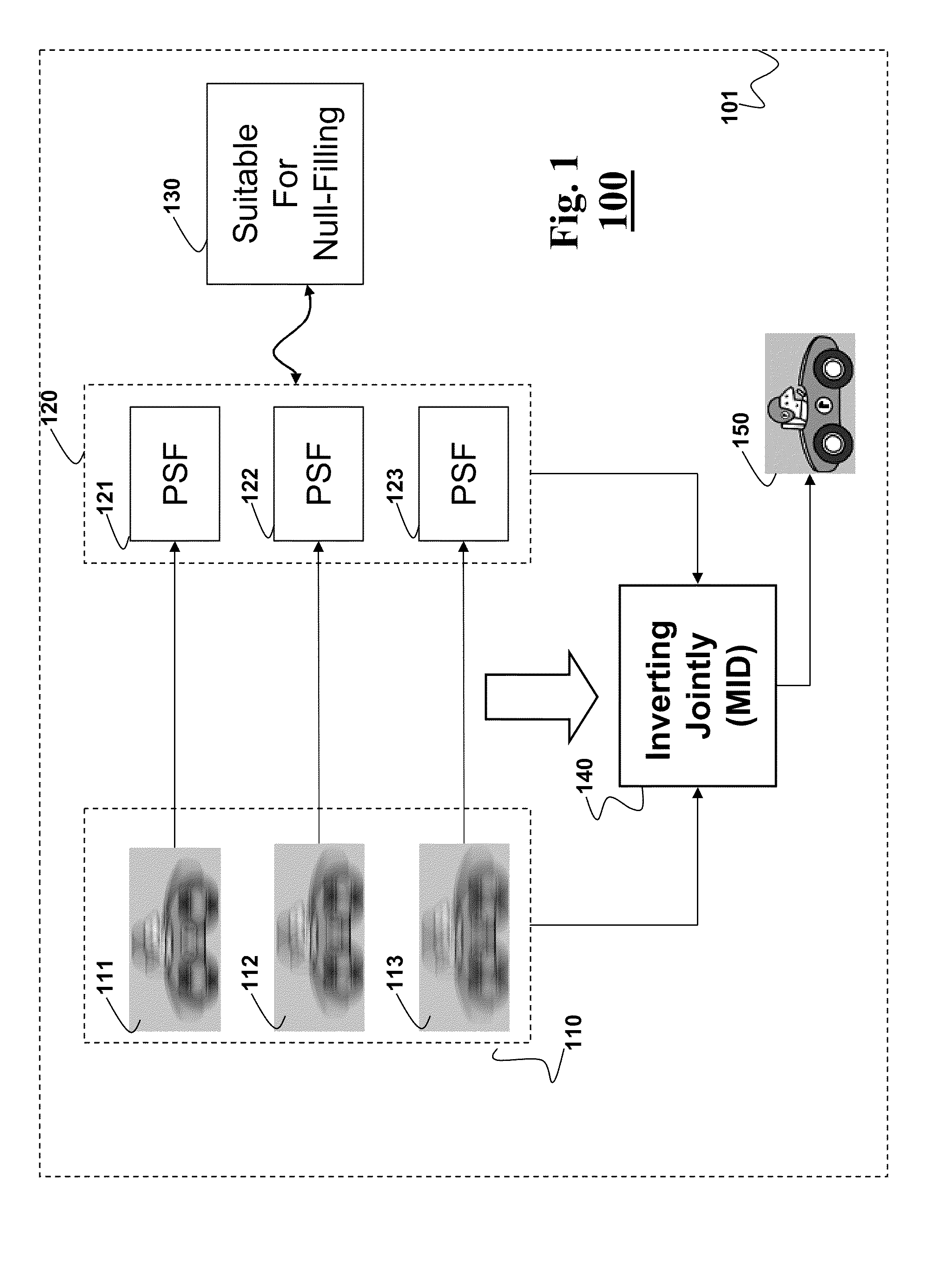
[0022]FIG. 1 shows a method 100 for multi-image deblurring of a set of images 110 of a scene according to embodiments of out invention. Each image 111-113 includes an object having a blur associated with a set 120 of point spread function (PSF) 121-123. The method inverts jointly 140 the set of images using the set of PSFs to produce an output image 150 having a reduced blur. The steps of the method are performed by a processor 101.

[0023]The images 110 are acquire by a camera such that the set of PSFs is suitable for a null-filling operation 130. The suitability is achieved by acquiring the images with different exposure times.

[0024]For example, in one embodiment, a first image 111 is acquired with a first exposure time, and a second image 112 is acquired with a second exposure time that is not an integer multiple of the first exposure time. In some embodiments, we use a conventional camera having an auto exposure bracketing (AEB). AEB enables the camera to take a sequence of images...


PUM


Abstract

Embodiments of the invention describe a method for reducing a blur in an image of a scene. First, we acquire a set of images of the scene, wherein each image in the set of images includes an object having a blur associated with a point spread function (PSF) forming a set of point spread functions (PSFs), wherein the set of PSFs is suitable for null-filling operation. Next, we invert jointly the set of images and the set of PSFs to produce an output image having a reduced blur.

Description

FIELD OF THE INVENTION [0001]This invention related generally to image processing, and more particularly to removing motion blur effects in images acquired of a moving object.BACKGROUND OF THE INVENTION [0002]Motion blurs result from relative motion between the camera and the scene while an image is acquired. Motion blurred images can be restored up to lost spatial frequencies by image deconvolution, provided that the motion is shift-invariant, at least locally, and that a blur function, also known as a point spread function (PSF), that caused the blur is known.[0003]Maintaining invertible motion PSF is not possible in conventional images. A box function due to a finite exposure time corresponds to a convolution with a low pass filter, and hence a frequency transform of the PSF contains zeros (nulls). The frequencies corresponding to the nulls of the PSF are lost, which makes the deblurring ineffective. Conventional methods use specialized cameras to determine the PSF.[0004]For exam...

Claims


Application Information

Patent Timeline
IPC IPC(8): G06K9/40
CPCG06T5/003G06T2207/20201G06T2207/10016G06T5/20G06T5/50G06T2207/10148
Inventor AGRAWAL, AMITXU, YIRASKAR, RAMESH
Owner MITSUBISHI ELECTRIC RES LAB INC
Why Eureka
Try Eureka