Method and a system for calibrating and/or visualizing a multi image display and for reducing ghosting artifacts

a multi-image display and artifact reduction technology, applied in the field of system and a method for calibrating and/or visualizing a multi-image display, can solve the problem of low resolution of arrangement, and achieve the effect of reducing ghosting artifacts and similar optical profiles

Inactive Publication Date: 2013-08-27
HUMANEYES TECH
View PDF84 Cites 43 Cited by
  • Summary
  • Abstract
  • Description
  • Claims
  • Application Information

AI Technical Summary

Benefits of technology

[0010]Optionally, the method further comprises using the blur profile reducing at least one ghosting artifact from the multi image display.
[0025]According to an aspect of some embodiments of the present invention there is provided a method for reducing artifacts of a multi image display. The method comprises displaying a calibration pattern through an image separating mask, allowing an evaluator to provide a visual estimation indicating a multi image display artifact brought about by the image separating mask, and processing a content image according to the visual estimation, thereby reducing the multi image display artifact.
[0032]According to an aspect of some embodiments of the present invention there is provided a system for identifying for a blur profile of a multi image display. The system comprises an input module configured for receiving a visual estimation of a blur brought about to a calibration pattern by at least an image separating mask, a calibrating module configured for generating the blur profile according to the visual estimation, and an output unit for outputting the blur profile, thereby allowing at least one of reducing a ghosting artifact of the multi image display and visualization the multi image display.
[0039]According to an aspect of some embodiments of the present invention there is provided a method for de-ghosting a multi image display having at least one image and a first image separating mask. The method comprises displaying a calibration pattern through an image separating mask, allowing a visual estimation of a blurring artifact brought about by a second image separating mask, and processing the at least one image according to the visual estimation, thereby reducing a ghosting artifact brought about at least by the first image separating mask. The first and second image separating masks having a substantially similar optical profile.

Problems solved by technology

However, this arrangement suffers from a low resolution.

Method used


Image

  • Method and a system for calibrating and/or visualizing a multi image display and for reducing ghosting artifacts
  • Method and a system for calibrating and/or visualizing a multi image display and for reducing ghosting artifacts
  • Method and a system for calibrating and/or visualizing a multi image display and for reducing ghosting artifacts

Examples


Embodiment Construction

[0059]The present invention, in some embodiments thereof, relates to a system and a method for calibrating and / or visualizing a multi image display and, more particularly, but not exclusively, to a system and a method for calibrating and / or visualizing a multi image display which are based on image separating masks.

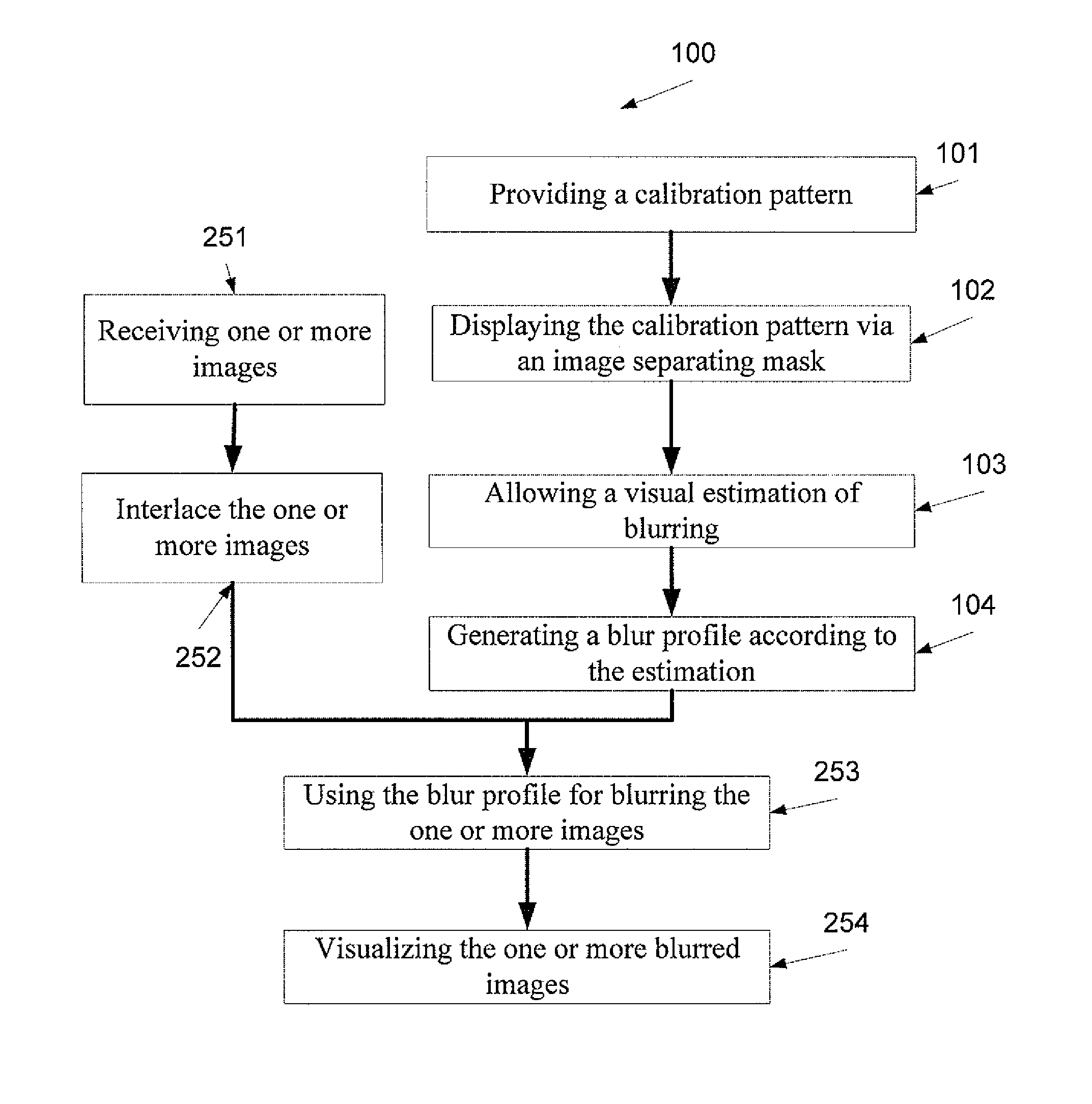
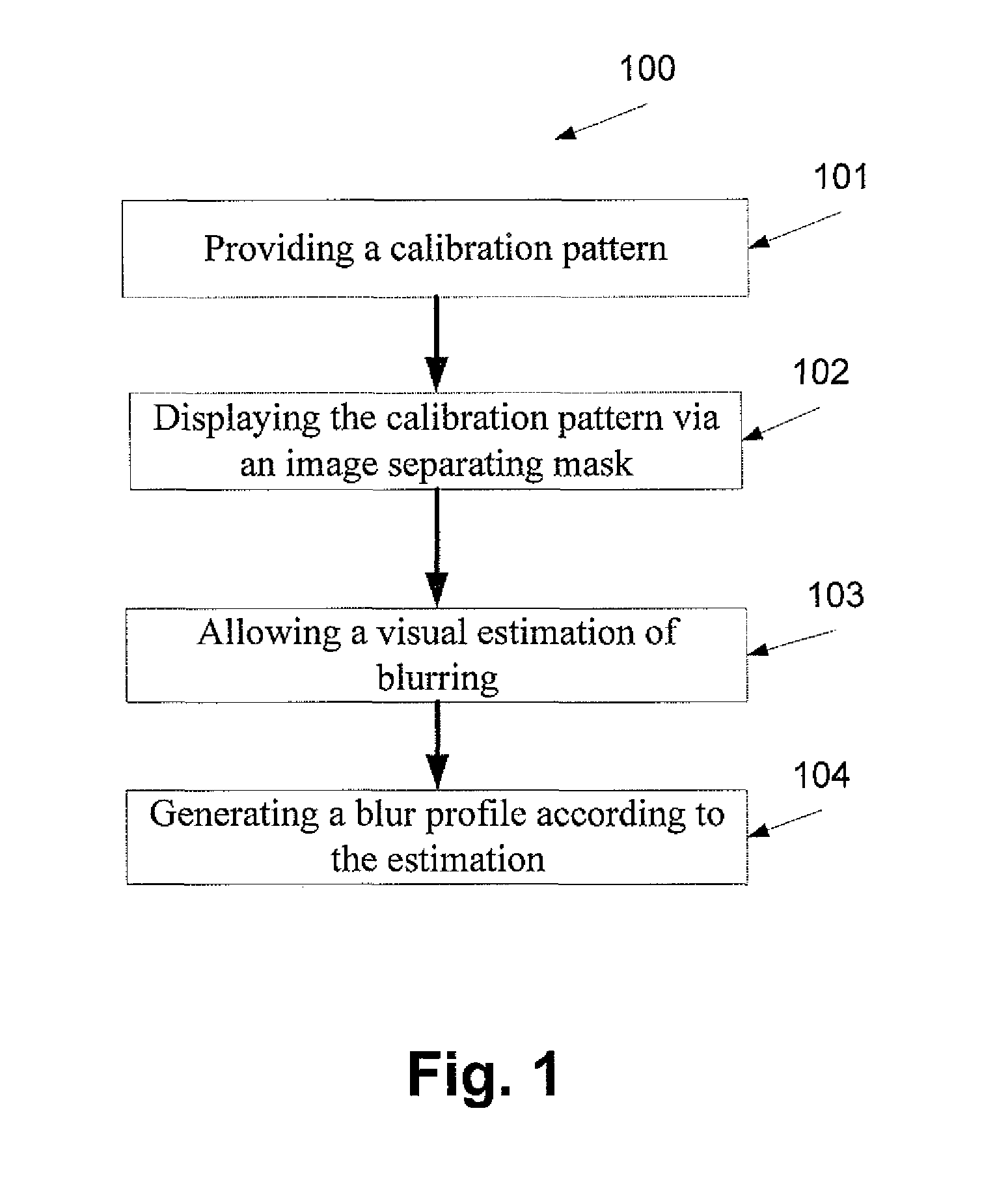
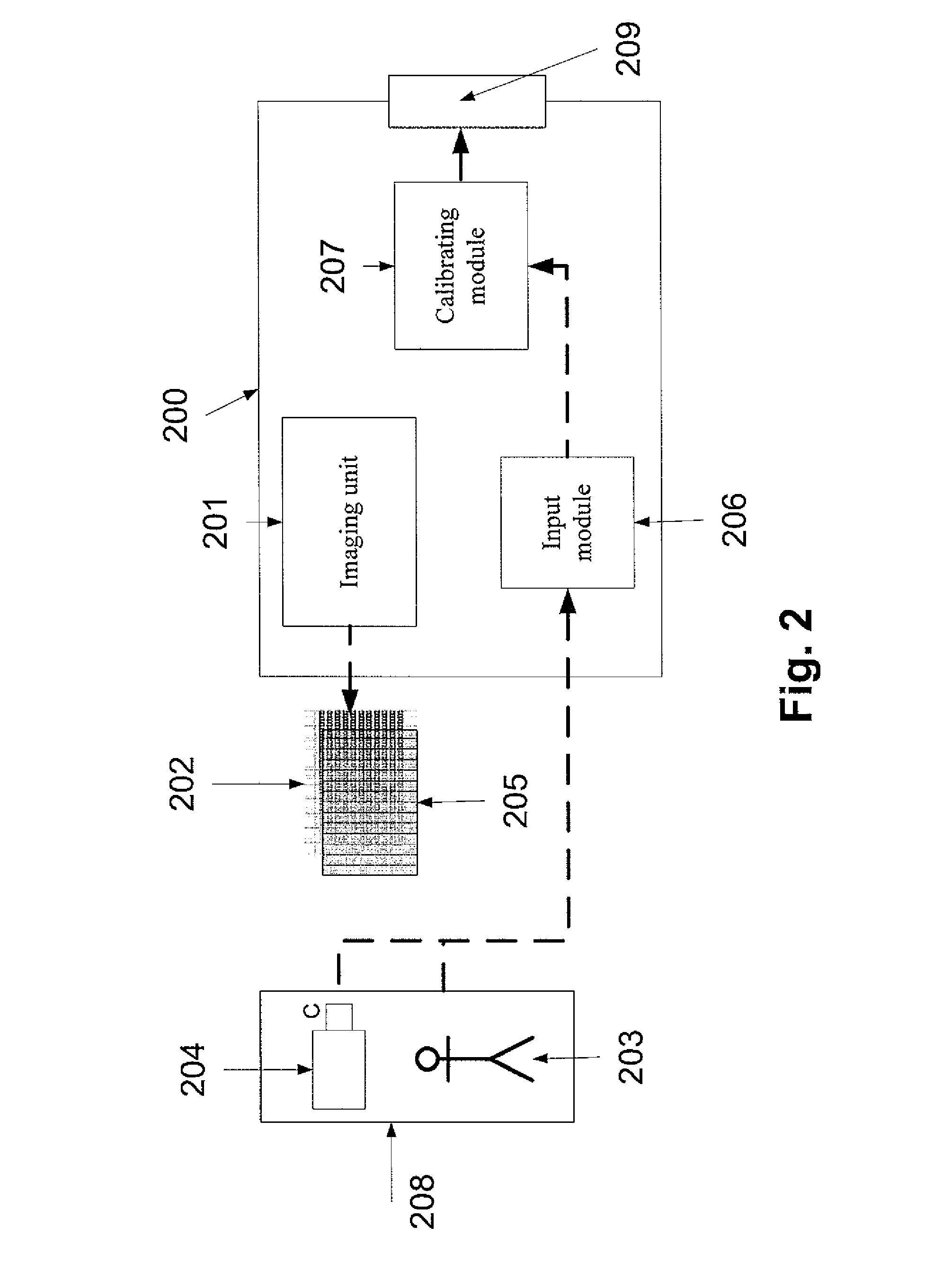
[0060]According to some embodiments of the present invention there is provided a method and a system for identifying one or more degradation profiles, such as a blur profile, that may be used for calibrating a multi image display. The method is based on a calibration pattern that is displayed to an evaluator, such as a system operator or an image capturing device, through a certain image separating mask. As used herein as an image separating mask means a lenticular lenses array, a parallax barrier, a multi image display screen, an array of lenses for integral photography (IP), for example as described in U.S. Pat. No. 5,800,907, filed on May 23, 1996 that is incorporated ...


PUM

PropertyMeasurementUnit
opticalaaaaaaaaaa
optical profileaaaaaaaaaa
refractive indexaaaaaaaaaa

Abstract

A method for identifying a blur profile of a multi image display with a first image separating mask. The method comprises displaying a calibration pattern through a second image separating mask, allowing an evaluator to provide a visual estimation indicating a blur brought about to the calibration pattern by the second image separating mask, and generating a blur profile of at least the first image separating mask according to the visual estimation. The first and second image separating masks having a substantially similar optical profile.

Description

RELATED APPLICATIONS[0001]This application is a National Phase Application of PCT Patent Application No. PCT / IL2008 / 000237 having International Filing Date of Feb. 25, 2008, which claims priority from U.S. Provisional Patent Application No. 60 / 891,512, filed on Feb. 25, 2007, U.S. Provisional Patent Application No. 60 / 951,242, filed on Jul. 23, 2007 and U.S. Provisional Patent Application No. 61 / 027,493, filed on Feb. 11, 2008. The contents of the above Application are all incorporated herein by reference.FIELD AND BACKGROUND OF THE INVENTION[0002]The present invention, in some embodiments thereof, relates to a system and a method for calibrating and / or visualizing a multi image display and, more particularly, but not exclusively, to a system and a method for calibrating and / or visualizing a multi image display which are based on image separating masks.[0003]In order to meet market demands, multi image displays must conform to the to high quality standards imposed on 2D displays. Us...

Claims


Application Information

Patent Timeline
Patent Type & Authority Patents(United States)
IPC IPC(8): G06T15/00G09G5/02G03F1/00A61M21/00G06K9/40G06K9/74G06K9/00G09G5/10H04N13/02H04N13/04H04N5/232G03H1/02G02B21/00G02B27/22G02B27/26G02B27/10G02B13/06G02B5/08G02B30/25
CPCH04N13/0404H04N13/0425G03B25/02G03B35/14G03B35/24H04N13/305H04N13/327
Inventor ZOMET, ASSAFELHARRAR, DANPRITCH, YAELHAVLIN, CHANOCHTADMOR, YARON
Owner HUMANEYES TECH
Why Eureka
Try Eureka