
Electric controlled type vehicular magnetic power driven brake

A magnetic braking, electronically controlled technology, applied in the deceleration device of DC motor, electric motor/converter plug, brake actuator, etc., can solve the problems of tire lock, unstable braking, low energy conversion efficiency, etc.

Inactive Publication Date: 2005-09-21
陈文杰
View PDF0 Cites 5 Cited by
  • Summary
  • Abstract
  • Description
  • Claims
  • Application Information

AI Technical Summary

Problems solved by technology

And existing various vehicles, as car, lorry, passenger car etc. all adopt the principle that brakes disc or brake drum to hold tightly friction to generate heat to brake without exception, although it can play a role in braking to a certain extent. effect, but it is easy to lock the tires. Although the ABS system alleviates the locking phenomenon to a certain extent, its principle and structure itself determine that the efficiency of energy conversion is very low, so the ABS system is increased. The moving distance is used to alleviate the locking phenomenon, and the point brake is adopted during braking, which makes the braking not smooth

Method used


Image

  • Electric controlled type vehicular magnetic power driven brake
  • Electric controlled type vehicular magnetic power driven brake
  • Electric controlled type vehicular magnetic power driven brake

Examples


Embodiment Construction

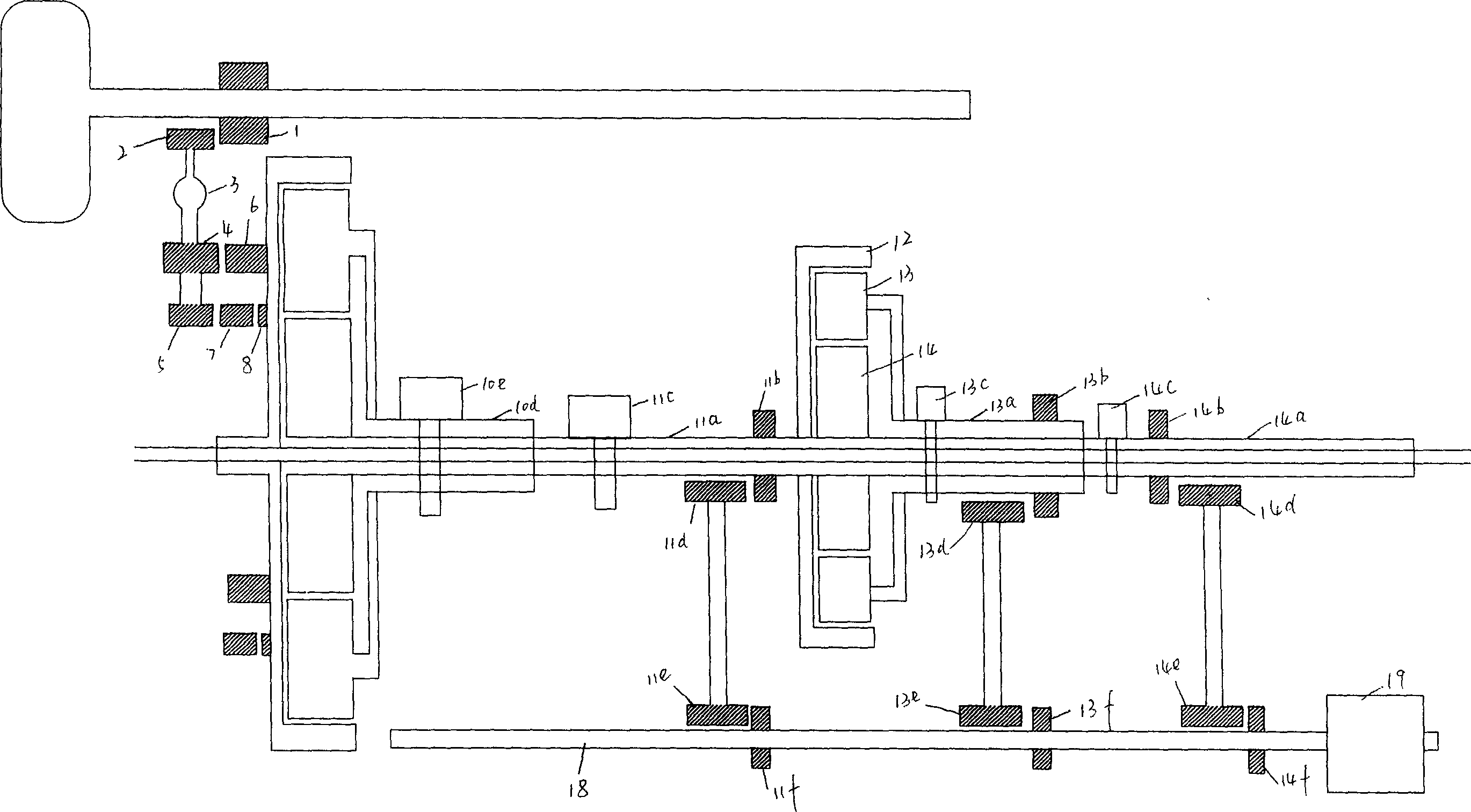
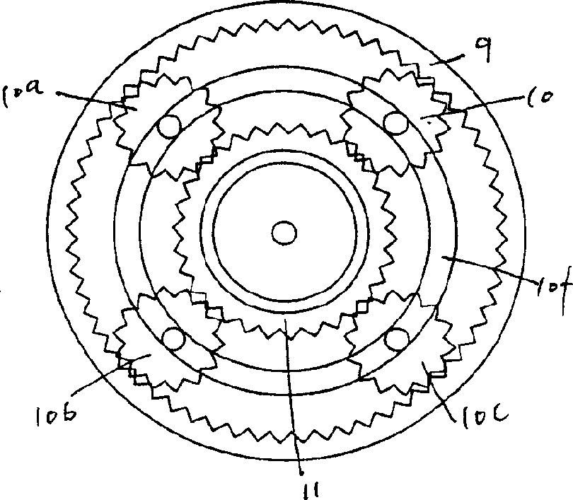
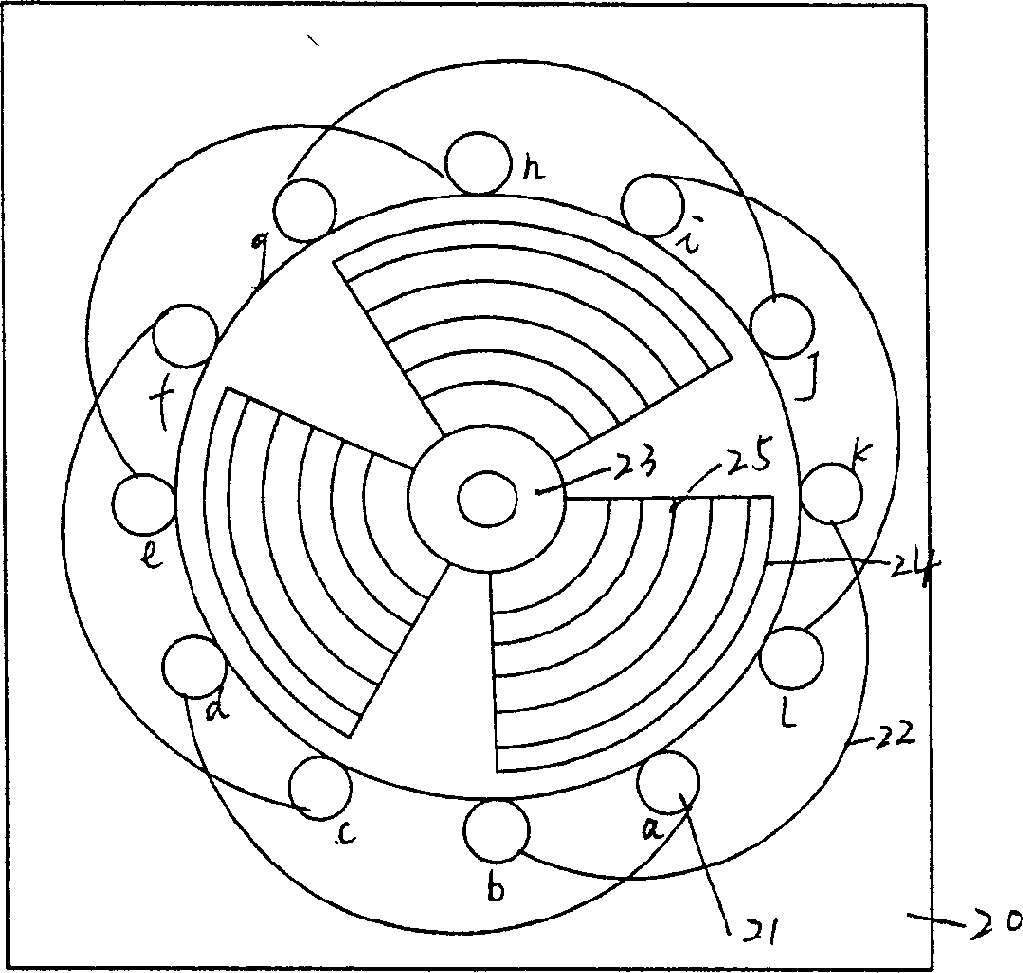
[0009] The invention is composed of three parts, namely an accelerator, a reluctance motor and a controller. The accelerator is composed of two rows of planetary rows and some driving gears and driven gears, such as figure 2 It is shown that the outer ring gear 9 of the first row of planets meshes with four planetary gears (gear 10, gear 10a, gear 10b and gear 10c), and the rotating shaft of each planetary gear is fixed on the planetary ring 10f, and the planetary ring It is fixedly connected with the hollow rotating shaft 10d through the metal connecting rod, and the hollow rotating shaft is provided with a fixer 10e (such as figure 1 As shown), the sun gear 11 is externally meshed with the planetary gear, and the drive shaft 11a fixedly connected with the sun gear is respectively provided with a driving gear 11b and a retainer 11c; the second planetary row, its external gear 12 and the first The transmission shaft 11a of the sun gear of the first row is fixedly connected, ...


PUM


Abstract

This invention relates to braking system of all kinds of autos. The existing braking equipment as brake disc and brake drum all adopts friction theory, but this invention adopts electromagnetic induction theory. Moment on auto half way around axis is transferred to reluctance machine after accelerated by accelerator, then energy brought by auto inertia is transformed into electrical energy by reluctance machine, the electrical energy is then transformed into heat energy of stator and rotor and other resistance of electric machine, so velocity of energy transform is accelerated greatly, braking distance is shortened and auto safety is increased.

Description

1. Technical field [0001] The invention relates to braking devices for various vehicles, especially using the principle of electromagnetic induction to convert the energy of the automobile due to inertia into electrical energy, and then convert the electrical energy into heat energy, thereby realizing non-contact braking between the braking device and the braked body idea. 2. Background technology [0002] With the development of modern industry, automobiles have become an indispensable part of people's lives. While people are pursuing high speed and speed, they pay more and more attention to the safety of automobiles, especially the braking performance of automobiles. And existing various vehicles, as car, lorry, passenger car etc. all adopt the principle that brakes disc or brake drum to hold tightly friction to generate heat to brake without exception, although it can play a role in braking to a certain extent. effect, but it is easy to lock the tires. Although the ABS s...

Claims


Application Information

Patent Timeline
Patent Type & Authority Applications(China)
IPC IPC(8): F16D65/28H02P3/12
Inventor 陈文杰
Owner 陈文杰
Learn More