Air exhaust brake butterfly valve control system and control method

A technology of exhaust braking and control system, applied in the direction of engine control, machine/engine, mechanical equipment, etc., can solve the problem of butterfly valve service life reducing friction power of engine air compressor and so on

Pending Publication Date: 2019-02-19
WEICHAI XIGANG NEW ENERGY POWER
View PDF10 Cites 0 Cited by
  • Summary
  • Abstract
  • Description
  • Claims
  • Application Information

AI Technical Summary

Problems solved by technology

In this way, the exhaust brake butterfly valve is 100% closed every time braking, which not only reduces the service life of the butterfly valve but also requires more friction work of the engine air compressor (air source)

Method used


Image

  • Air exhaust brake butterfly valve control system and control method
  • Air exhaust brake butterfly valve control system and control method
  • Air exhaust brake butterfly valve control system and control method

Examples


Embodiment Construction

[0031] The present invention will be described in further detail in conjunction with the accompanying drawings and embodiments.

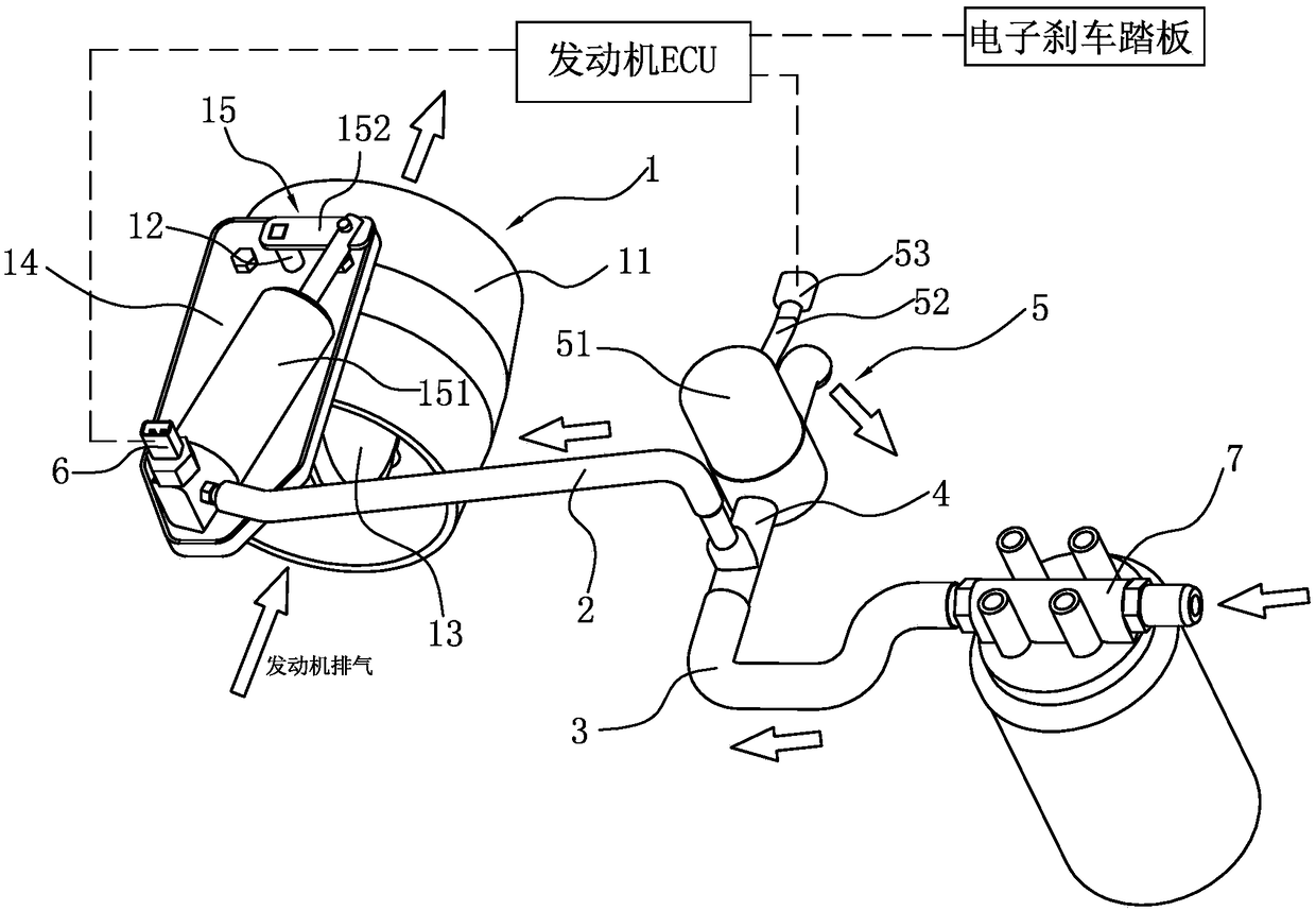
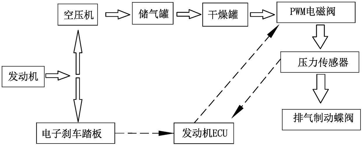
[0032] Such as figure 1 with figure 2 As shown together, the exhaust brake butterfly valve control system is mainly composed of exhaust brake butterfly valve 1, PWM solenoid valve 5 (PWM is the abbreviation of Pulse Width Modulation, representing pulse width modulation) and an electronic brake pedal that provides users with braking needs.

[0033] The valve body 11 of the exhaust brake butterfly valve 1 is arranged on the engine exhaust pipe. The valve shaft 12 is rotatably installed on the valve body 11. One end of the valve shaft 12 passes through the wall surface of the valve body 11 and the butterfly plate 13 inside the valve body 11. Fixedly connected, the valve body 11 is also provided with a mounting plate 14, the other end of the valve shaft 12 (the end outside the wall of the valve body 11) passes through the mounting plate 14, and the mo...


PUM


Abstract

The invention discloses an air exhaust brake butterfly valve control system and control method. The control system comprises an air exhaust brake butterfly valve, a PWM electromagnetic valve on a pressure relief pipe segment and an electronic brake pedal, wherein a pneumatic actuator of the air exhaust brake butterfly valve communicates with a driving air inlet pipe segment, the driving air inletpipe segment communicates with both an air supplying pipe segment and the pressure relief pipe segment, the air supplying pipe segment communicates with an air source device, the pneumatic actuator orthe driving air inlet pipe segment is provided with a pressure sensor, and the pressure sensor, the PWM electromagnetic valve and the electronic brake pedal are all in electric connection with an engine ECU. According to the air exhaust brake butterfly valve control system and control method, on base of the position of the electronic brake pedal, the engine ECU finds out the driving air inlet pressure calibration value and the pulse width value in sequence, the opening of the PWM electromagnetic valve is adjusted in real time till a pressure actual measurement valve is equal to the driving air inlet pressure calibration value, the air exhaust brake butterfly valve blocks air exhaust to achieve the purpose of braking under driving of air inlet pressure, and by means of the air exhaust brake butterfly valve control system and control method, the opening of the air exhaust brake butterfly valve can be controlled on base of brake requirement power.

Description

technical field [0001] The invention belongs to the technical field of engine brake systems, and in particular relates to an exhaust brake butterfly valve control system and control method for engines. Background technique [0002] The requirements for the vehicle braking system in the new standard of the "Technical Conditions for Motor Vehicle Operation Safety" GB7258 put forward that trucks and dangerous goods transport vehicles over 12 tons will be forced to install retarders or other auxiliary braking devices. This regulation determines that truck braking must meet the requirements, which can only be accomplished by trucks equipped with retarders, and the installation of other non-retarder auxiliary braking devices alone cannot meet the requirements of this regulation. The retarder auxiliary braking devices mainly used in trucks now include: exhaust brake butterfly valve, hydraulic retarder, in-cylinder brake, etc. [0003] Most of the brake system structures of truck e...

Claims


Application Information

Patent Timeline
IPC IPC(8): F02D9/10F02D11/08
CPCF02D9/10F02D11/08
Inventor 周胜余
Owner WEICHAI XIGANG NEW ENERGY POWER
Why Eureka
Try Eureka