Shorting switch and system to eliminate arcing faults in power distribution equipment

A short-circuit switch, flashover fault technology, applied in electrical switches, circuit devices, emergency protection circuit devices, etc., can solve problems such as expensive purchase and maintenance

Inactive Publication Date: 2005-09-21
EATON CORP
View PDF1 Cites 21 Cited by
  • Summary
  • Abstract
  • Description
  • Claims
  • Application Information

AI Technical Summary

Problems solved by technology

Known short circuit switches use make and hold techniques,

Method used


Image

  • Shorting switch and system to eliminate arcing faults in power distribution equipment
  • Shorting switch and system to eliminate arcing faults in power distribution equipment
  • Shorting switch and system to eliminate arcing faults in power distribution equipment

Examples


Embodiment Construction

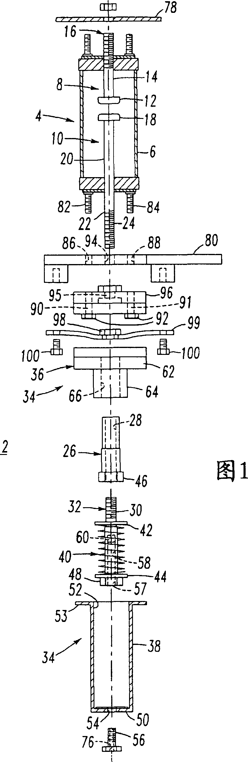
[0052] Referring to Figure 1, a single phase, spring loaded, high speed vacuum short circuit switch 2 eliminates flashover faults within a power distribution device (not shown). The shorting switch 2 comprises a single vacuum switch, such as a conventional vacuum interrupter (VI) 4 (e.g., a 3" VI bottle manufactured by Eaton / Catella-Hammer). As is known, the vacuum interrupter 4 comprises a vacuum-tight enclosure or A sealed vacuum chamber (e.g., a vacuum bottle 6) that contains a fixed contact assembly 8 and a movable contact assembly 10 that can be in electrical contact with the fixed contact assembly 8. Movement along the longitudinal axis is between a closed circuit position (not shown) and an open circuit position (shown in FIG. 1 ) spaced apart from the fixed contact assembly 8 .

[0053] The fixed contact assembly 8 includes a fixed contact 12 sealed in the airtight vacuum bottle 6 and a conductor 14 connected to one end of the fixed contact. The electrical conductor 1...


PUM


Abstract

A shorting switch (2) includes a vacuum switch (4) having fixed and movable contact assemblies (8, 10) and a driven member (26). A spring cover tube (38) and bushing (36) mount the driven member (26) for linear movement along a path substantially parallel to a longitudinal axis of the movable contact assembly (10). The driven member (26) moves the movable contact assembly (10) between open and closed circuit positions. A compression spring (40) has a compressed state and a released state, which moves the driven member (26) and movable contact assembly (10) to the closed circuit position. A release bolt (32) has an opening (68) therein and is coupled to the driven member (26) to normally maintain the compression spring (40) in the compressed state. A charge (60) is disposed in the opening of the release bolt (32) and is actuated to fracture the release bolt and release the compression spring (40) to the released state. First and second terminals (16, 22) are respectively electrically interconnected with the fixed and movable contact assemblies (8, 10).

Description

[0001] Cross References to Related Applications [0002] This application is related to the following commonly assigned, concurrently filed applications: [0003] U.S. Patent Application No.__ / ______, filing date _ / ______, 2002, titled "____________________" (Attorney Docket No. 01-EDP-213); [0004] U.S. Patent Application No.__ / ______, filing date __ / ______, 2002, titled "Shorting Switch And System To Eliminate Arcing Faults In LowVoltage Power Distribution Equipment" (Attorney Docket No. 01-EDP-385); [0005] U.S. Patent Application No.__ / ______, filing date __ / ______, 2002, titled "Shorting Switch And System To Eliminate Arcing Faults In LowVoltage Power Distribution Equipment" (Attorney Docket No. 01-EDP-386); [0006] U.S. Patent Application No.__ / ______, filing date __ / ______, 2002, titled "Bullet Assembly For A Vacuum Arc Interrupter" (Attorney Docket No. 01-EDP-425); [0007] U.S. Patent Application No.__ / ______, filing date __ / ______, 2002, titled "Vacuum Arc Interru...

Claims


Application Information

Patent Timeline
IPC IPC(8): H01H3/30H01H33/666H01H39/00H01H79/00H02H1/00
CPCH01H3/3031H01H39/00H01H33/666H02H1/0023H01H2003/3036H01H79/00
Inventor J·J·谢伊J·A·米勒
Owner EATON CORP
Why Eureka
Try Eureka