Socket device for electric parts

A technology for electrical components and sockets, applied to coupling devices, electrical components, incandescent lamp parts, etc., can solve the problems of weak elasticity of the contact terminals 11 and reduced reliability of the socket device, achieve miniaturization, prevent deformation of the contact terminals, High reliability effect

Inactive Publication Date: 2005-09-28
ALPS ALPINE CO LTD
View PDF0 Cites 0 Cited by
  • Summary
  • Abstract
  • Description
  • Claims
  • Application Information

AI Technical Summary

Problems solved by technology

However, in the case of such a structure, the elastic force of the contact terminal 11 becomes weaker, so that the contact pressure on the contact portion 15 of the electrical component 13 becomes smaller. From a viewpoint different from the above, the reliability of the socket device as a socket device becomes weaker. decreased sex

Method used


Image

  • Socket device for electric parts
  • Socket device for electric parts
  • Socket device for electric parts

Examples


Embodiment Construction

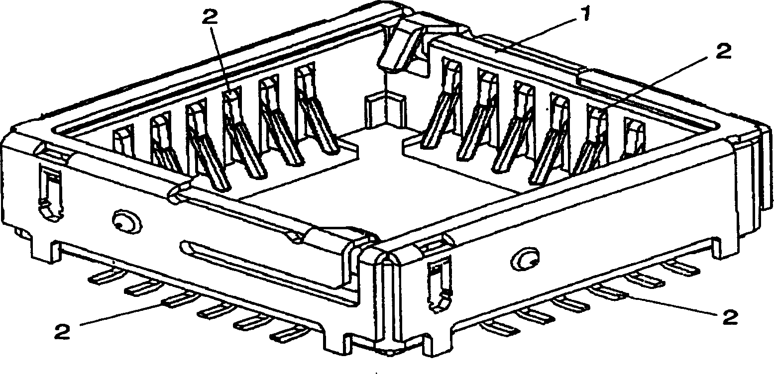
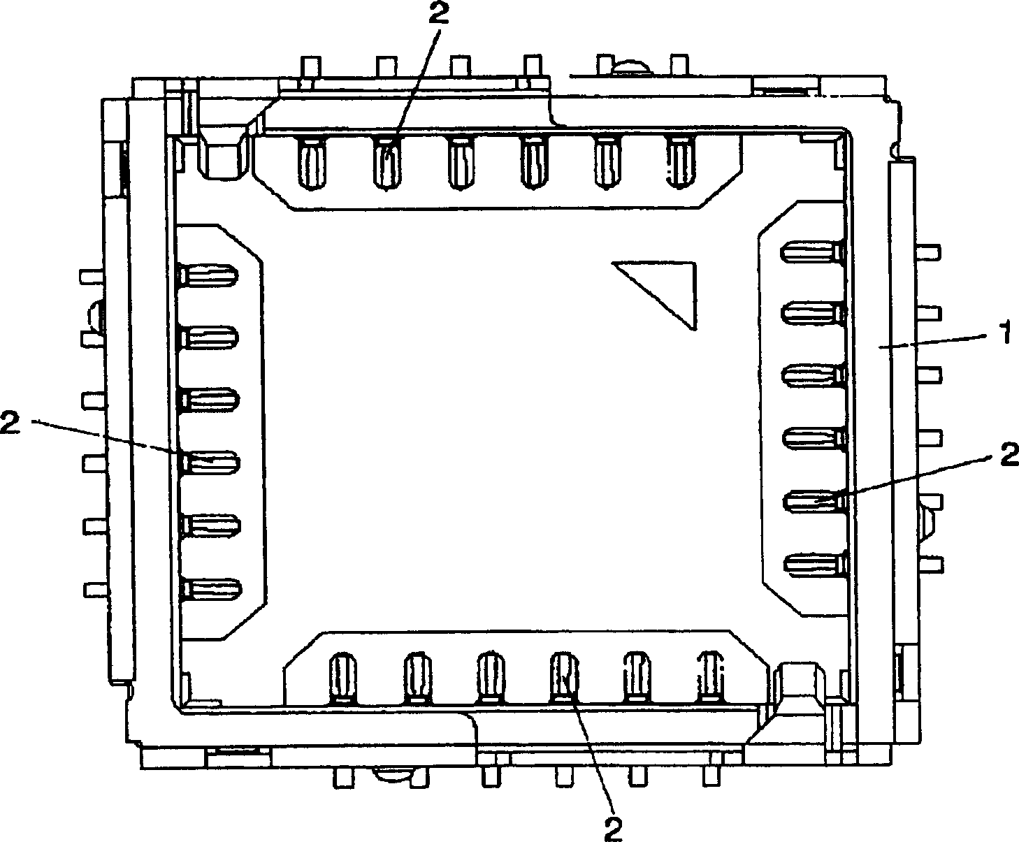
[0032] Next, the best mode for implementing the electrical component socket device related to the present invention will be described based on the drawings.

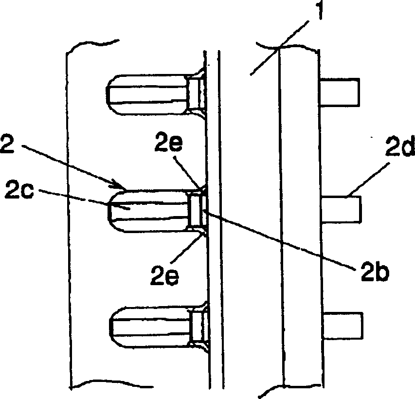
[0033] figure 1 It is a perspective view of an embodiment of the present invention, figure 2 yes figure 1 A top view of one embodiment shown, image 3 yes figure 2 A partially enlarged schematic diagram. Figure 4 yes figure 1 A longitudinal sectional view of an embodiment shown, Figure 5 yes Figure 4 A partially enlarged schematic diagram. Figure 6 yes figure 1 (a) is a top view, (b) is a front view, (c) is a perspective view, and (d) is a side view in explanatory drawing of the contact terminal in the shown embodiment.

[0034] Such as Figure 1~5 As shown, in this embodiment, there is, for example, a housing 1 whose overall shape is square, and the inner walls of the four sides of the housing 1 respectively have contact portions 5 formed in grooves 4 of electrical components 3 described later. Mult...


PUM


Abstract

To enable to evade mutual interference between a protruding part positioned between groove parts, in which the contact parts of electrical components are formed and the top part of a contact terminal, without weakening the spring force of the contact terminal. This is provided with a housing 1, in which a plurality of the groove parts 4 where the contact parts 5 to be electrically connected are respectively formed and the electric components 3, having the protruding part 3a formed between the groove parts 4 are mounted; and there are further provided with a plurality of contact terminals 2 which are equipped in the housing 1, and with which the respective contact parts 5 are connected; and at the top parts 2b of the contact terminals 2 is a skirt part 2e, having a part in which the distance between the facing electrical components 3 becomes farther, when the electrical part 3 is mounted on the housing 1.

Description

technical field [0001] The present invention relates to a socket device for an electrical component having a plurality of contact terminals respectively connected to a plurality of contact portions formed on the electrical component in a case in which the electrical component is mounted. Background technique [0002] As such prior art, for example, the technique described in Patent Document 1 is known. Figure 11 It is an explanatory diagram showing a conventional electrical component socket device described in Patent Document 1. FIG. [0003] Such as Figure 11 The shown conventional socket device is provided on a printed circuit wiring board 12 and has a plurality of contact terminals on each of the inner walls of the four sides of the housing 10 , which is a housing whose overall shape is square. The electrical component 13 mounted in the case 10 contains an IC circuit, and grooves 14 are formed on each of the four sides. In each groove portion 14 is formed a contact por...

Claims


Application Information

Patent Timeline
Patent Type & Authority Applications(China)
IPC IPC(8): H01R33/76H01R12/55
CPCF04C18/0215F04C18/0269F04C23/008F04C29/0021F04C2210/26F04C2240/30Y10S415/00Y10S417/902
Inventor 荻野哲治小口亘佐佐木弘
Owner ALPS ALPINE CO LTD
Why Eureka
Try Eureka