Superconducting magnet apparatus

A technology of superconducting magnets and superconducting coils, which is applied in the direction of superconducting magnets/coils, measuring devices, magnetic objects, etc., and can solve problems such as failure to prevent damage to coil containers and no consideration

Inactive Publication Date: 2005-10-19
HITACHI LTD
View PDF2 Cites 18 Cited by
  • Summary
  • Abstract
  • Description
  • Claims
  • Application Information

AI Technical Summary

Problems solved by technology

However, in Patent Document 2, when the pipeline from the coil container to the outside of the vacuum container freezes to form a blockage, damage to the coil container due to quench phenomenon or vacuum breakage is not considered.
In additio...

Method used


Image

  • Superconducting magnet apparatus
  • Superconducting magnet apparatus
  • Superconducting magnet apparatus

Examples


no. 1 Embodiment

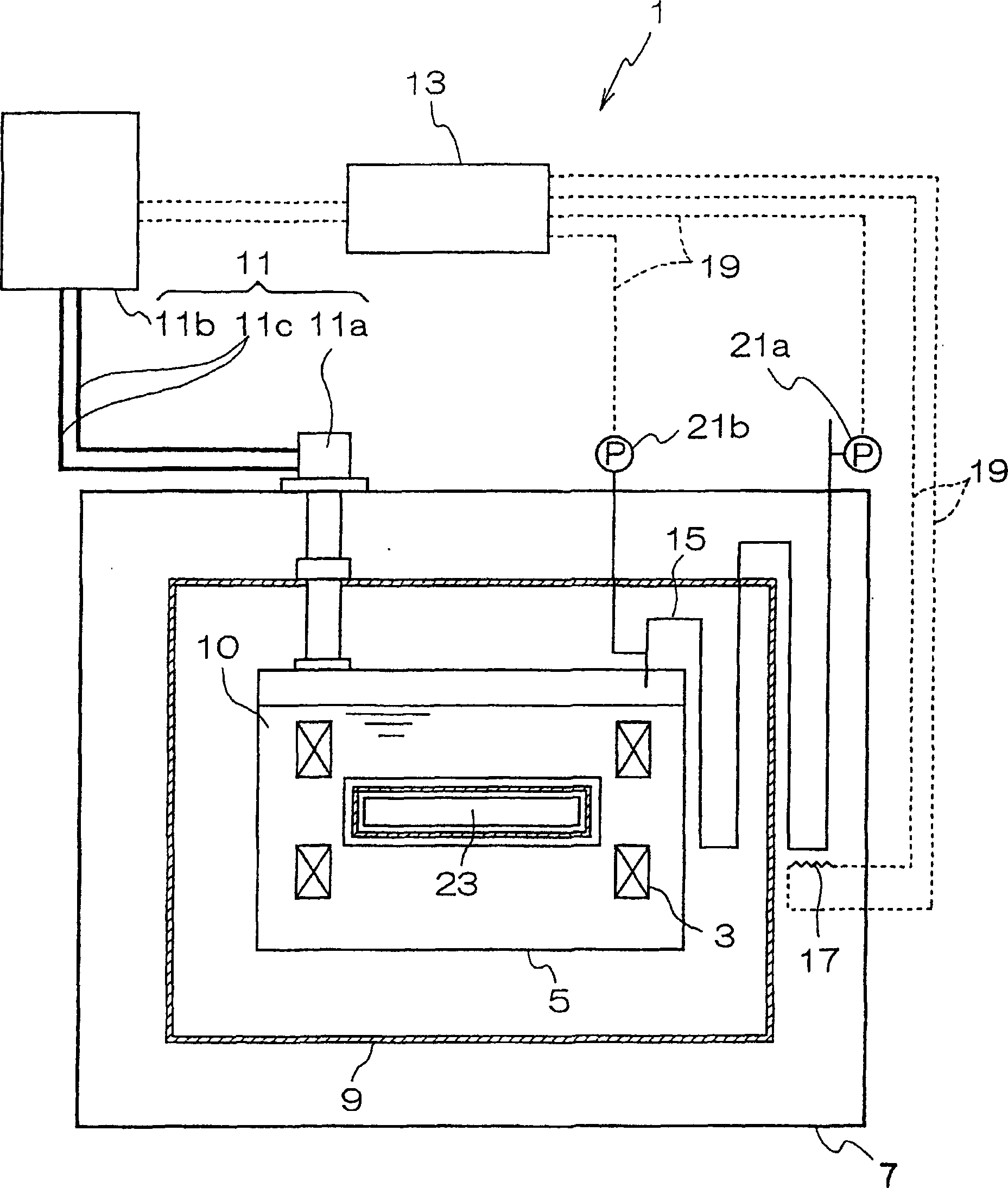
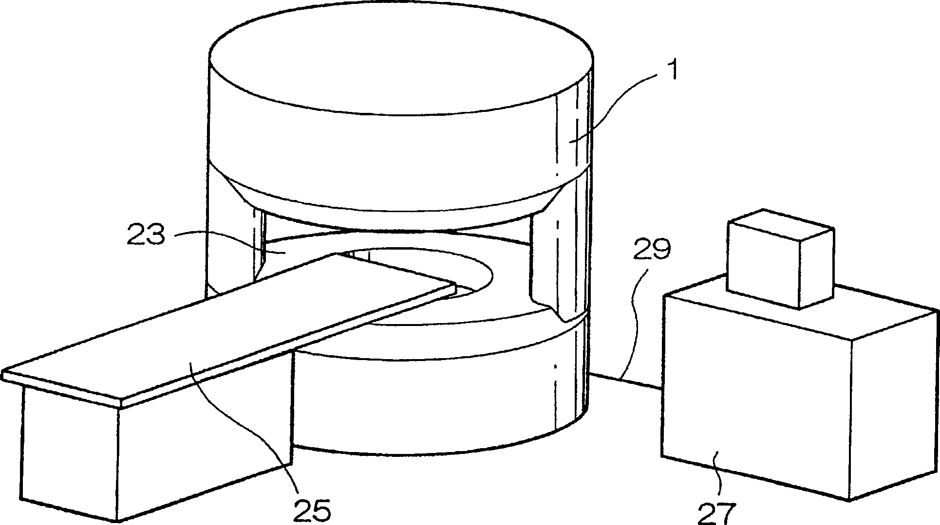
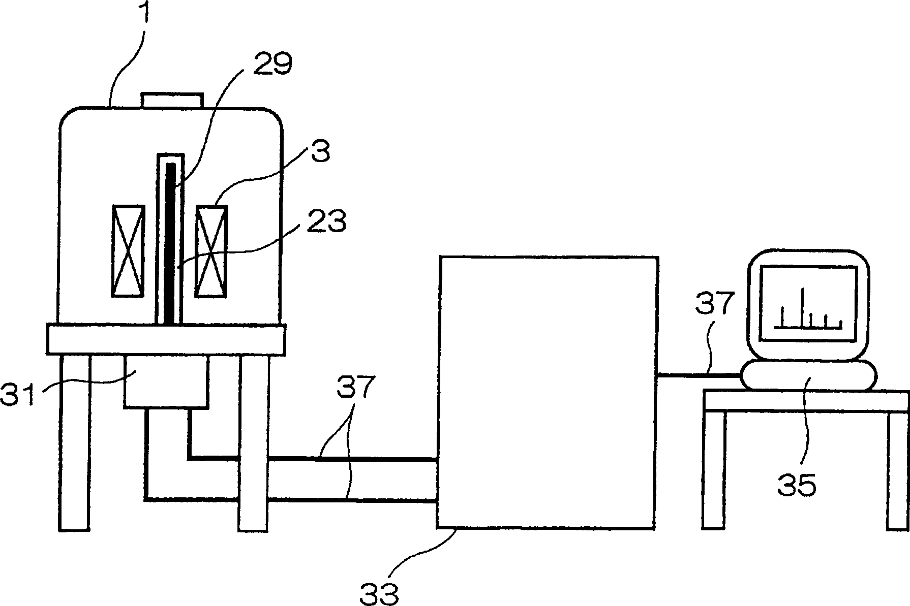
[0043] Below, refer to Figure 1 to Figure 6 An example of a superconducting magnet device to which the present invention is applied will be described. figure 1 It is a sectional view showing a schematic structural model of a superconducting magnet device to which the present invention is applied. figure 2 It is a perspective view showing a schematic structural model of a magnetic resonance imaging apparatus equipped with a superconducting magnet apparatus to which the present invention is applied. image 3 It is a block diagram showing a schematic structural model of a nuclear magnetic resonance apparatus equipped with a superconducting magnet apparatus to which the present invention is applied. Figure 4 ~ Figure 6 It is a schematic diagram showing a schematic structure of a superconducting magnet device to which the present invention is applied, and is a cross-sectional view showing various examples of positions where electric heaters are installed.

[0044] The supercon...

no. 2 Embodiment

[0067] Below, refer to figure 1 A second embodiment to which the superconducting magnet device of the present invention is applied will be described. In addition, in this embodiment, the description of the same structure as that of the first embodiment is omitted, and only the structure or features different from the first embodiment will be described.

[0068] The difference between the superconducting magnet device of this embodiment and the first embodiment is that the control unit stops cooling the refrigerant in the coil container by the refrigerator when the pressure in the coil container exceeds a set pressure. And, when the pressure in the coil container exceeds the set pressure, the control unit energizes the electric heater to heat the pipeline. That is, the superconducting magnet device 1 of the present embodiment is the same as figure 1 The structure of the first embodiment shown is the same. However, the controller 13, when the pressure of the connection side p...

no. 3 Embodiment

[0077] Below, refer to Figure 7 A third embodiment to which the superconducting magnet device of the present invention is applied will be described. Figure 7 It is a cross-sectional view showing a schematic structural model of a superconducting magnet device to which the present invention is applied. In addition, in this embodiment, the same symbols are used for the same structures as those of the first and second embodiments, and their descriptions are omitted, and only the structures or features different from those of the first and second embodiments will be described.

[0078] The difference between the superconducting magnet device of this embodiment and the first and second embodiments is that the purification electric heater installed in the liquid-phase refrigerant in the coil container is connected to the control unit forming the heating mechanism together with the electric heater, When the pressure in the coil container is lower than the set pressure, the purifica...


PUM


Abstract

The invention obtains a superconductive magnet device for preventing damage to a coil container caused by the occurrence of a quench phenomenon, vacuum break or the like, when blocking by freezing is generated in a pipeline for connecting the coil container to the outside of a vacuum container. The superconductive magnet device comprises the coil container for accommodating a superconductive coil and a liquefied refrigerant for cooling the superconductive coil to a critical point or smaller, the vacuum container for performing the vacuum heat insulation of the coil container from the outside by including the coil container, and the pipeline whose one end communicates with the inside of the coil container and the other end is located outside the vacuum container. A heating means for heating the pipeline is provided at least at one location of a part piped to the inside of the vacuum container in the pipeline. Even if a constituent for causing freezing in air or the like in the pipeline enters for freezing, the heating means heats the pipeline for melting freezing and for canceling the blocking of the pipeline.

Description

technical field [0001] The present invention relates to a superconducting magnet device in which a superconducting coil is accommodated in a coil container and a liquefied refrigerant for cooling the superconducting coil to a critical point or lower is accommodated. Background technique [0002] In a superconducting magnet arrangement, the superconducting coil is cooled by a liquefied refrigerant, such as liquid helium, which is used to cool the superconducting coil below the critical point. Therefore, the cryostat of the superconducting magnet device accommodates the refrigerant in the coil container together with the superconducting coil, and the coil container is wrapped in a vacuum container forming a vacuum layer for vacuum insulation. In addition, the so-called pipe for injecting the refrigerant into the coil container and the pipe for discharging the gas-phase refrigerant in the coil container to the outside of the coil container are properly connected to the coil con...

Claims


Application Information

Patent Timeline
IPC IPC(8): G01R33/3815A61B5/055H01F6/00H01F6/02H01F6/04H01F27/14H01F27/40
CPCH01F6/02F25D19/00F25D29/006H01F6/04H01F27/14H01F2027/406
Inventor 古闲康则渡边洋之池田孝志
Owner HITACHI LTD
Why Eureka
Try Eureka