Femur center location method based on hand eye type robot

A robot and femur technology, applied in surgery, medical science, etc., can solve the problem of large positioning error of the femoral center, and achieve the effect of improving accuracy, low complexity, and simple steps

Inactive Publication Date: 2005-10-26
SHANGHAI JIAO TONG UNIV
View PDF1 Cites 5 Cited by
  • Summary
  • Abstract
  • Description
  • Claims
  • Application Information

AI Technical Summary

Problems solved by technology

[0004] The purpose of the present invention is to address the deficiencies in the prior art and propose a method for positioning the center of t

Method used


Image

  • Femur center location method based on hand eye type robot
  • Femur center location method based on hand eye type robot
  • Femur center location method based on hand eye type robot

Examples


Embodiment Construction

[0015] In order to better understand the technical solutions of the present invention, a further detailed description will be made below in conjunction with the accompanying drawings and embodiments.

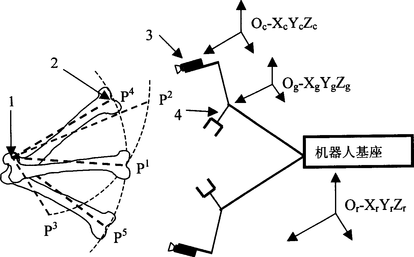
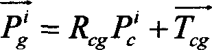
[0016] 1. Use Tsai's method to calibrate the hand-eye robot, and obtain the robot's hand-eye position transformation relationship, that is, the rotation matrix and translation vector between the robot's claw coordinate system and the camera coordinate system. Let the rotation matrix and translation vector of the camera coordinate system obtained by calibration relative to the paw coordinate system be R cg and

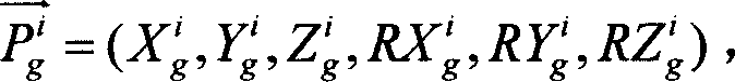
[0017] 2. Collect the coordinates of the center of the intercondylar notch and the data of the paw posture. Fix the upper body and hip of the patient to keep the center of the femur unchanged, and the distal part of the femur is exposed. Bend the knee 90 degrees forward, and record the position of the distal end of the femur as the initial position P 1 , move the cla...


PUM


Abstract

A method based on the hand-eye robot for locating the center of femur includes calibrating the hand and eye of robot by Tsai method to obtain the their position transform relation, simultaneously moving the far end of femur and the camera fixed to the hand jaw of robot to make the center of fossa intercondyloidea in the vision field of camera in large covered spherical range, acquiring the data about said center and hand jaw state at each position, converting the data to the coordinate system based on robot, fitting the data to a spherical equation, and calculation.

Description

technical field [0001] The invention relates to a femur center positioning method based on a hand-eye robot, which is used for CT-free robotic total knee joint replacement surgery. It belongs to the field of advanced manufacturing and automation (medicine). Background technique [0002] In our country, thousands of patients with severe arthritis need total knee replacement every year. Total knee arthroplasty is a typical artificial prosthesis implantation operation in orthopedic surgery. The most basic and important concept is to establish the precise force line of the lower limbs, that is, the center of the femoral head, the center of the knee joint (or the center of the intercondylar fossa) and the center of the ankle joint. The center should be in the same straight line, and only through calculated and accurately measured osteotomy can the accurate reconstruction of the lower extremity line of force be obtained. At present, the determination of the force line of the low...

Claims


Application Information

Patent Timeline
IPC IPC(8): A61B17/56
Inventor 石繁槐张婧刘允才
Owner SHANGHAI JIAO TONG UNIV
Why Eureka
Try Eureka