A Penning Ion Source Based on Hollow Cathode Discharge

A technology of hollow cathode discharge and Penning ion source, applied in the direction of discharge tube, ion beam tube, circuit, etc., can solve the problems of coating pollution, affecting the insulation of ion source, easy pollution, etc., to reduce pollution and increase effective movement Stroke, the effect of improving stability

Active Publication Date: 2021-02-19
嘉兴艾钛科纳米科技有限公司
View PDF4 Cites 0 Cited by
  • Summary
  • Abstract
  • Description
  • Claims
  • Application Information

AI Technical Summary

Problems solved by technology

However, the gap between the anode and the cathode of the ion source on the anode layer is small, and the coating device is easily polluted, which affects the insulation of the ion source. At the same time, there is ablation corrosion on the cathode, which is easy to pollute the coating.

Method used


Image

  • A Penning Ion Source Based on Hollow Cathode Discharge
  • A Penning Ion Source Based on Hollow Cathode Discharge
  • A Penning Ion Source Based on Hollow Cathode Discharge

Examples


Embodiment 1

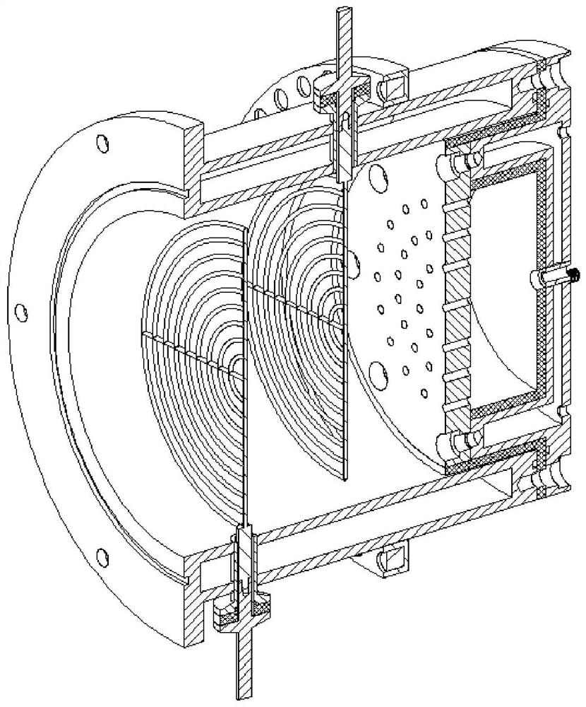
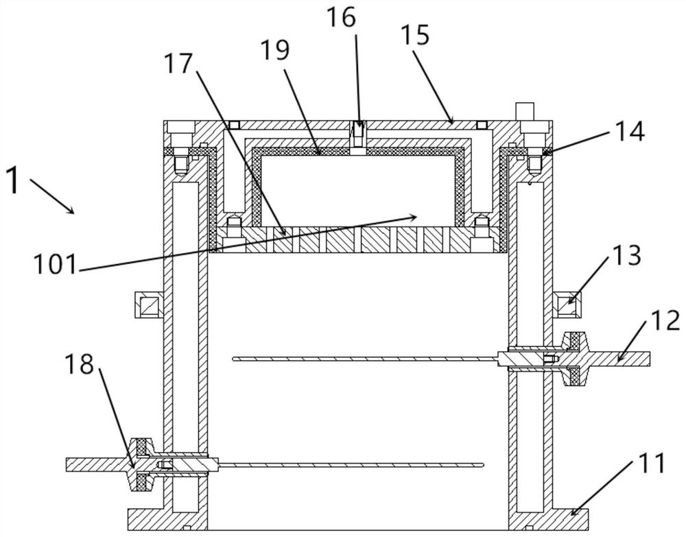
[0040] see Figure 4.1 As shown: the magnetic field of the magnetic pole 13 is a single-polarity magnetic field formed by a permanent magnet, and the single-polarity magnetic field is a magnetic group formed by magnets of the same polarity that is set on the anode cylinder 11, and its magnetic field direction is parallel to the axial direction Under the action of a single polar magnetic field, the electrons move spirally under the influence of the magnetic field, which increases the effective stroke in the discharge chamber of the anode cylinder, increases the number of collisions with the process gas, and generates more electrons at the same time.

[0041] see Figure 6 Shown:

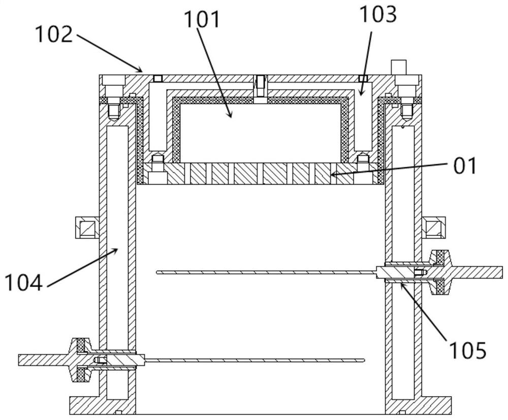
[0042] The hollow cathode plate 17 is provided with a plurality of groups of holes 01, the hollow cathode plate 17 and the cathode grid 12 are applied with the negative voltage of the same potential, the anode cylinder 11 is loaded with positive electricity, and the accelerating pole 18 is loaded wit...

Embodiment 2

[0049] The difference between the magnetic poles of this embodiment and the first embodiment is that the magnetic field of the magnetic pole 13 is an electromagnetic coil, which provides a stable and controllable electromagnetic field for the electron source. The electromagnetic coil is a conventional single-phase wound electromagnetic coil, on which various waveforms such as sine, cosine, square wave, and triangle wave can be applied, and a load with adjustable frequency and current can be formed in the anode cylinder 11 correspondingly. With a certain oscillating magnetic field, the movement of electrons in the oscillating magnetic field can further increase the effective movement distance compared with a single polarity magnetic field, and can collide with more process gases to generate more electrons.

[0050] see Figure 4.2 As shown: the magnetic field of the magnetic pole 13 is the magnetic field of the electromagnetic coil formed by the permanent magnet. The magnetic g...


PUM

PropertyMeasurementUnit
thicknessaaaaaaaaaa
diameteraaaaaaaaaa

Abstract

The invention discloses a Penning ion source based on a hollow cathode discharge, which comprises: an anode cylinder, a cathode net, a magnetic pole, an insulating sleeve, a cathode seat, an air inlet, a hollow cathode plate, an accelerating pole, and a ceramic sleeve. The holes on the hollow cathode plate are used to gather electrons during the glow discharge process to produce a hollow cathode effect, which can form a Penning discharge between the anode cylinder and the cathode grid, and the electrons can realize reciprocating motion under the action of the electric field and magnetic field. The movement stroke is greatly elongated, and more electrons are generated by the collision, and are accelerated by the accelerating pole to output a large beam of particle flow into the vacuum chamber. The cathode seat and the anode cylinder are equipped with water-cooled chambers, which can efficiently discharge during the discharge process. At the same time, a large number of microporous ceramic sleeves can realize the stability of the intake air flow; the present invention realizes uniform and stable discharge by combining Penning discharge and hollow cathode discharge, and can have a better cooling effect and improve ion discharge. Long-term high-efficiency stability of the source.

Description

technical field [0001] The invention relates to a Penning ion source, in particular to a Penning ion source based on hollow cathode discharge. Background technique [0002] The ion source is the most widely used ion-assisted deposition at this stage, and a device that discharges ionized gas through plasma during the vapor deposition process of cleaning the product to be plated. The ion source can effectively improve the density and adhesion of the film layer, as well as the optical and mechanical properties of the film layer. The commonly used ion sources at this stage mainly include Penning ion source, Hall ion source, and anode layer ion source. [0003] The Penning ion source is an ion source designed on the basis of Penning discharge. By applying a magnetic field in the axial direction of the annular anode, the electrons move back and forth between the two cathodes to increase the ionization rate of gas particles. The Penning ion source The principle causes the structu...

Claims


Application Information

Patent Timeline
Patent Type & Authority Patents(China)
IPC IPC(8): H01J27/04H01J27/02
CPCH01J27/022H01J27/04
Inventor 郎文昌
Owner 嘉兴艾钛科纳米科技有限公司
Why Eureka
Try Eureka