Floor conveying equipment especially fork load-unload car

A technology for ground transportation and loading and unloading trucks, which is applied to forklifts, transportation and packaging, and motor vehicles. It can solve the problems of poor stability of ground transportation equipment and achieve high reliability and low cost.

Active Publication Date: 2005-11-02
斯蒂尔公司
View PDF1 Cites 12 Cited by
  • Summary
  • Abstract
  • Description
  • Claims
  • Application Information

AI Technical Summary

Problems solved by technology

When turning and driving, a stable roll angle is achieved through multiple large swings, resulting in poor stability of the ground conveying equipment

Method used


Image

  • Floor conveying equipment especially fork load-unload car
  • Floor conveying equipment especially fork load-unload car
  • Floor conveying equipment especially fork load-unload car

Examples


Embodiment Construction

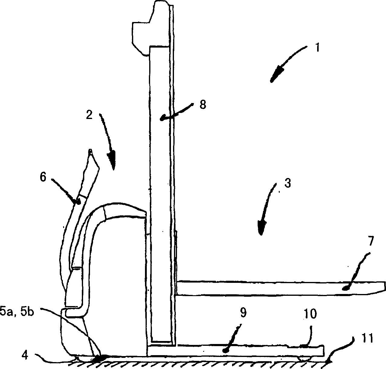
[0029] figure 1 A floor conveying device 1 constructed as a high-lift forklift truck towed by a drawbar is given in , which includes a drive part 2 and a load-carrying part 3 . The drive part 2 has a drive wheel 4 arranged centrally with respect to the longitudinal axis of the floor conveyor 1 and two turning rollers 5a, 5b arranged laterally. The drive wheel 4 can be guided by means of a drawbar 6 . The carrying part 3 includes a carrying arm 7 which is arranged on the lifting device 8 and can move up and down. The carrier part 3 also includes two spokes 9 , each of which accommodates a carrier roller 10 configured as a simple roller or a tandem roller. The floor conveyor 1 is thus supported on the running rail 11 by means of the drive wheels 4 , the turning rollers 5 a , 5 b and the carrier rollers 10 .

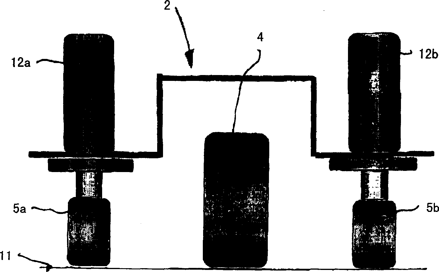
[0030] figure 2 gives figure 1 Schematic structure of the drive part 2 of the ground conveying device 1 . A steerable drive wheel 4 is secured to the drive part 2 in...


PUM


Abstract

The present invention relates to an earth-conveying equipment (1), especially a fork lift truck which comprises a driving part (2) and a bearing part (3), wherein, the area of the bearing part (3) is arranged with at least two bearing rollers (10), the area of the driving part (2) is arranged with at least one rotatable driving wheel (4) and at least one rotating roller (5a and 5b) which can rotate around one vertical axis and are arranged while the vertical movement is allowed and are supported by means of one spring shock absorbing device (12a and 12b). To improve the stability of the earth-conveying equipment the spring shock absorbing device (12a and 12b) comprises a shock absorbing device which functions when the rotating roller (5a and 5b) suspending protrudes and suspending retreat, especially a hydraulic shock absorbing device, and / or the spring shock absorbing device (12a and 12b) comprises a transition spring characteristic curve.

Description

technical field [0001] The invention relates to a floor conveyor, in particular a forklift truck, which has a drive part and a carrying part. In this case, at least two carrier rollers are arranged in the region of the carrier part, while at least one steerable drive wheel and at least one turning roller are arranged in the region of the drive part. The latter is rotatable about a vertical axis and arranged vertically movable and is supported by means of a spring damper. Background technique [0002] Such floor conveyors are known, for example, as traction-rod shared carriages, or as trolleys with a lifting platform having a driver's station or driver's seat. The load-carrying part of a floor conveyor of this type is supported on the running rail by means of two load-carrying rollers. The drive part is then supported on the running rail with drive wheels, which are preferably fixed rigidly to the floor conveyor. In order to increase the stability, at least one turning rol...

Claims


Application Information

Patent Timeline
Patent Type & Authority Applications(China)
IPC IPC(8): B66F9/06B66F9/075B66F9/22
CPCB66F9/07586B66F9/07572B60G2300/022B60G17/005
Inventor 米夏埃尔·霍克法比奥·马里奥蒂
Owner 斯蒂尔公司
Why Eureka
Try Eureka