Refrigeration system and method for detecting quantity of refrigerant of refrigeration system

A technology of freezing device and amount of refrigerant, used in refrigerators, refrigeration components, refrigeration and liquefaction, etc.

Active Publication Date: 2005-11-02
DAIKIN IND LTD
View PDF1 Cites 16 Cited by
  • Summary
  • Abstract
  • Description
  • Claims
  • Application Information

AI Technical Summary

Problems solved by technology

[0021] Moreover, the occurrence of this kind of phenomenon is not limited to the occasion where the working refrigerant is selected as R410A, even if R407C is used, when the outside air temperature is high and the refrigerant condensation tempera

Method used


Image

  • Refrigeration system and method for detecting quantity of refrigerant of refrigeration system
  • Refrigeration system and method for detecting quantity of refrigerant of refrigeration system
  • Refrigeration system and method for detecting quantity of refrigerant of refrigeration system

Examples


Embodiment 1

[0054] (1) The overall structure of the air conditioner

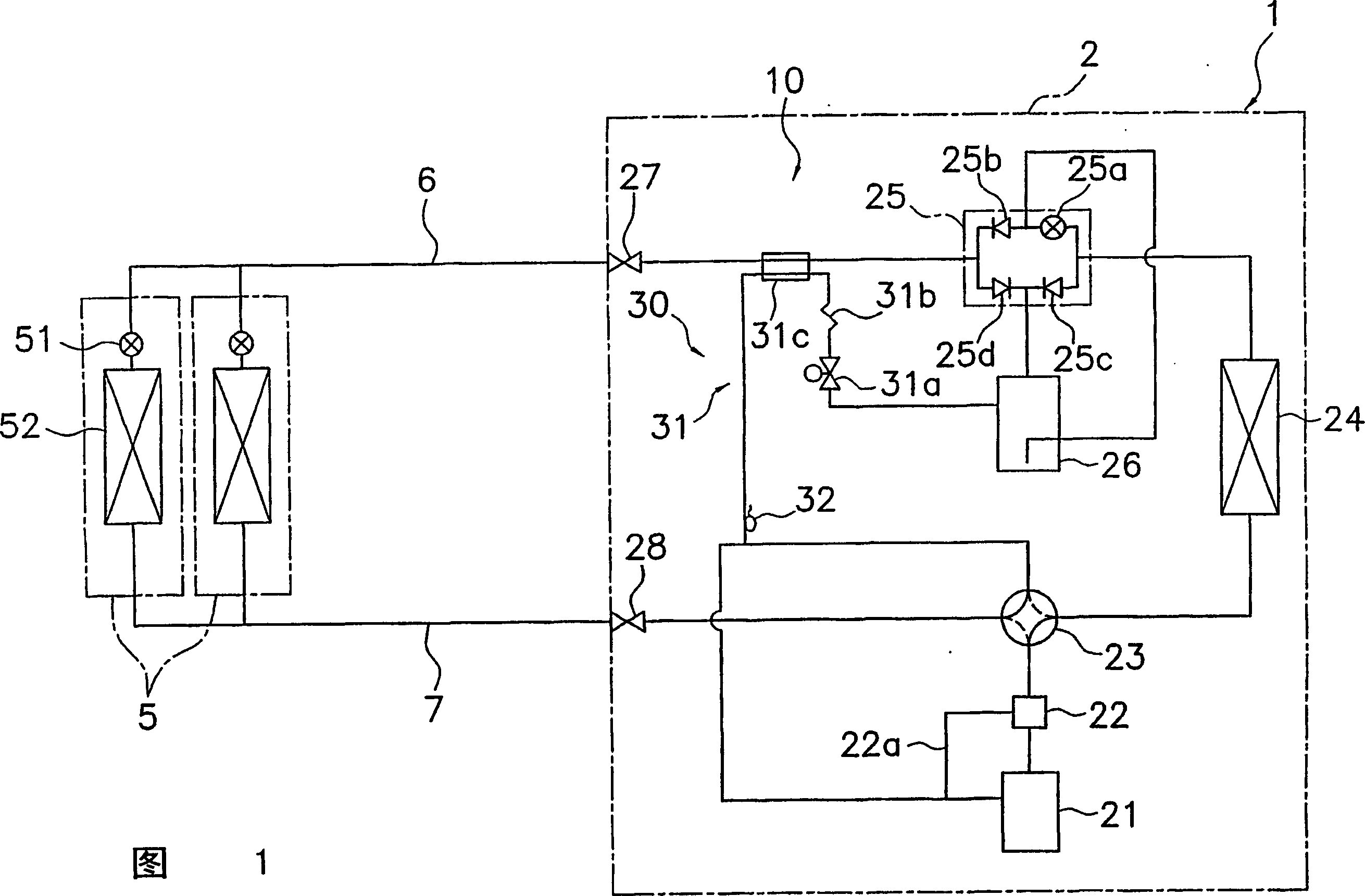
[0055]Fig. 1 is a schematic diagram of a refrigerant circuit of an air conditioner 1 according to Embodiment 1, which is an example of a refrigeration system according to the present invention. Like the conventional air conditioner 901, the air conditioner 1 is equipped with one heat source unit 2, several (here, two) use units 5 connected in parallel thereto, and a liquid for connecting the heat source unit 2 and the use unit 5. The connecting pipe 6 for refrigerant and the connecting pipe 7 for gas refrigerant. Here, the configuration of the heat source unit 2 other than the utilization unit 5 and the liquid level detection circuit 30 , that is, the configuration of the main refrigerant circuit 10 is the same as that of the conventional air conditioner 901 , so description thereof will be omitted, and only the configuration of the liquid level detection circuit 30 will be described. constitute.

[0056] The liquid l...

example 2

[0082] In the liquid level detection circuit 30, a heating mechanism 31c composed of a heat exchanger using liquid refrigerant as a heat source is provided, but as shown in FIG. The communication circuit 231 includes a heating mechanism 231c for heating the refrigerant by an external heat source such as an electric heater. Even so, the same effect as that provided by the liquid level detection circuit 30 can be obtained.

[0083] (6) Modification 3

[0084] In the liquid level detection circuit 30, a heating mechanism 31c composed of a heat exchanger using liquid refrigerant as a heat source is provided, but as shown in FIG. The liquid level detection circuit 330 of the circuit 331 and the bypass circuit 331 include a heating mechanism 331c utilizing the heat dissipation of the engine. Even so, the same effect as that provided by the liquid level detection circuit 30 can be obtained.

[0085] (7) Modification 4

[0086] In the liquid level detection circuit 30, a heating m...

Embodiment 2

[0088] In the air conditioner 1 of Embodiment 1, only the first predetermined position L of the accumulator 26 corresponding to the required amount of refrigerant at the time of refrigerant charging 1 A liquid level detection circuit 30 is provided, but in order to determine whether the liquid storage tank 26 is full of liquid, the second predetermined position L at the top of the liquid storage tank 26 can also be 2 A liquid level detection circuit having the same configuration as the liquid level detection circuit 30 is provided at the place.

[0089] It is also possible to store the liquid refrigerant at the reference position L at the bottom of the liquid storage tank 26 all the time. R An auxiliary liquid level detection circuit having the same structure as the liquid level detection circuit 30 is set at the place.

[0090] Specifically, the structure of the main refrigerant circuit 10 and the liquid level detection circuit 30 of the air conditioner 501 of this embodimen...


PUM


Abstract

A refrigeration system comprising a refrigerant circuit including a compressor and a receiver in which the judgment accuracy of a liquid level detecting circuit for judging whether liquid refrigerant is stored up to a specified position of the receiver is enhanced. An air conditioner (1) comprises a main refrigerant circuit (10) and the liquid level detecting circuit (30). The main refrigerant circuit (10) comprises a compressor (21) for compressing gas refrigerant, a heat-source-side heat exchanger (24), the receiver (26) for storing liquid refrigerant, and a utilization-side heat exchanger (52). The liquid level detecting circuit (30) is arranged to take out a part of refrigerant in the receiver (26) from a first fixed position (L1) thereof, to reduce the pressure thereof while heating, and to return the refrigerant back to the suction-side of the compressor (21) after measuring the refrigerant temperature, thus detecting the fact that the liquid level in the receiver has reached the first fixed position (L1).

Description

technical field [0001] The present invention relates to a refrigerating device and a method for detecting the amount of refrigerant in the refrigerating device, and more particularly to a refrigerant circuit including a liquid storage tank for storing liquid refrigerant by a compressor for compressing gas refrigerant. A refrigeration device and a refrigerant quantity detection method for the refrigeration device. Background technique [0002] As a conventional refrigerating apparatus including a vapor compression refrigerant circuit, there is an air conditioner for air conditioning a building or the like, for example. This air conditioner mainly includes a heat source unit having a compressor and a heat source side heat exchanger, several utilization units having a utilization side heat exchanger, and connecting piping for gas refrigerant and connecting piping for liquid refrigerant connecting these units. . [0003] At the construction site, when each unit and piping of t...

Claims


Application Information

Patent Timeline
IPC IPC(8): F25B1/00F25B13/00F25B45/00F25B49/02
CPCF25B2400/23F25B13/00F25B2400/13F25B2313/0272F25B2400/19F25B2700/04F25B45/00F25B2400/16F25B2500/01F25B1/00
Inventor 水谷和秀松冈弘宗
Owner DAIKIN IND LTD
Why Eureka
Try Eureka