Electric clippers

An electric clipper and electromagnet technology, applied in metal processing and other directions, can solve problems such as aggravating noise and increasing operator discomfort, and achieve the effects of reducing vibration energy, vibration noise, and vibration.

Inactive Publication Date: 2005-11-09
于会成
View PDF0 Cites 3 Cited by
  • Summary
  • Abstract
  • Description
  • Claims
  • Application Information

AI Technical Summary

Problems solved by technology

The disadvantage is that the armature reciprocates quickly left and right, and because the electromagnet is fixed on the shell, the vibration of the armature, bracket, and moving blade is directly transmitted to the shell, and then transmitted to the operator's hand
Housing vibration also exacerbates noise, both of which increase operator discomfort

Method used


Image

  • Electric clippers

Examples


Embodiment approach

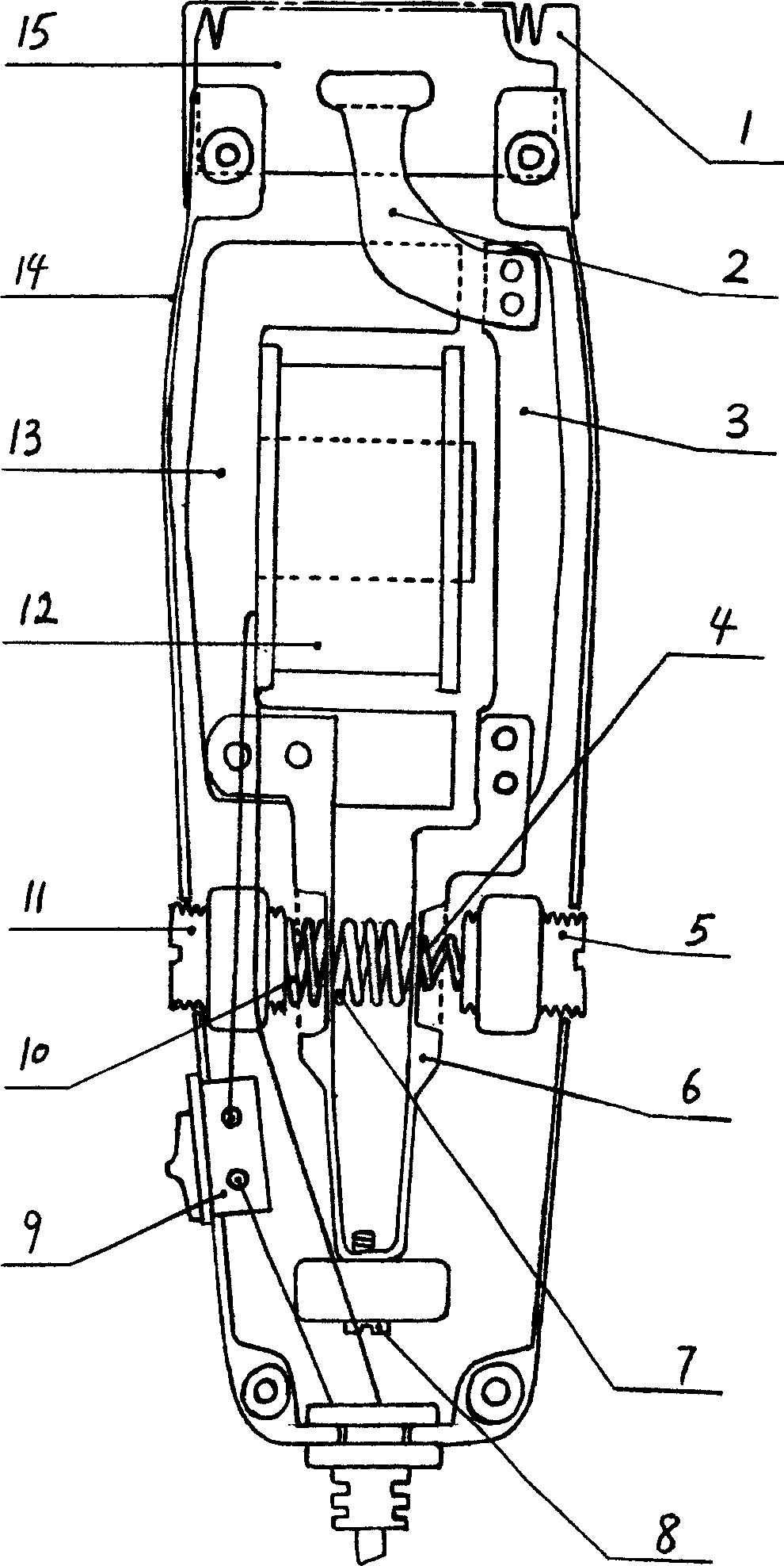
[0017] One embodiment of the present invention is as follows: the housing 1 is made of plastic molding. The fixed blade 1 is made of a metal material, and the front end is provided with scissor teeth. The fixed blade is fixed to the front end of the housing by screws. Moving blade 15 adopts metal material to make, and front end has scissors, has hole in the middle of moving blade, and its effect is to insert for the wear-resistant plastic of leaf spring 2 front ends, and wear-resistant plastic also plays further safe insulating effect. Since the upper ends of the leaf spring 2 and the armature 3 are fixedly connected, the left and right swing of the armature will drive the left and right movement of the movable blade through the leaf spring 2 . The bracket 6 is made of steel plate stamped and bent into a "V" shape. One branch is fixedly connected to the lower end of the electromagnet core 13, and the other branch is fixedly connected to the lower end of the armature 3. The lo...


PUM


Abstract

An electromagnetic hair-clippers with low vibration and noise features that its electromagnet and armature are respectively supported by two elastic supporters, a spring is arranged between said two supporters, and two springs are used to link said supporters to the regulating scrows at both sides of casing.

Description

technical field [0001] The invention discloses an electric clipper for hairdressing, which consists of a fixed blade 1, a spring piece 2, an armature 3, an armature end spring 4, an adjustment screw 5, a bracket 6, an intermediate spring 7, a screw 8, a switch 9, and an iron core end. Electromagnet, housing 14, moving blade 15 etc. that spring 10, adjusting screw 11, coil 12 and iron core 13 are formed. Background technique [0002] The electromagnetic hair clipper widely used at present adopts the principle of electromagnetic vibration to periodically attract the armature through the energized electromagnet and drive the moving blade to move relative to the fixed blade to realize cutting of the hair. The disadvantage is that the armature reciprocates quickly left and right, and because the electromagnet is fixed on the shell, the vibration of the armature, bracket, and moving blade is directly transmitted to the shell, and then transmitted to the operator's hand. Housing v...

Claims


Application Information

Patent Timeline
Patent Type & Authority Applications(China)
IPC IPC(8): B26B19/06
Inventor 于会成
Owner 于会成
Why Eureka
Try Eureka