
Reflective optical assembly

A light reflection and projection system technology, applied in the field of projection systems, can solve the problems of heavy glass optical elements, chromatic aberration of refracting optical elements, and high production costs

Inactive Publication Date: 2005-11-09
HEWLETT PACKARD DEV CO LP
View PDF0 Cites 1 Cited by
  • Summary
  • Abstract
  • Description
  • Claims
  • Application Information

AI Technical Summary

Problems solved by technology

Glass optics are heavy, made of more expensive materials, and are more expensive to manufacture
In addition, due to the dispersion properties of refractive optical materials, refractive optical elements are prone to chromatic aberration

Method used


Image

  • Reflective optical assembly
  • Reflective optical assembly
  • Reflective optical assembly

Examples


Embodiment Construction

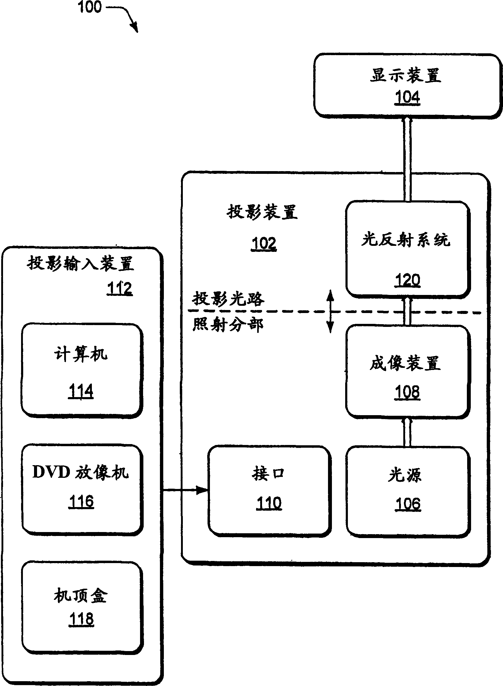
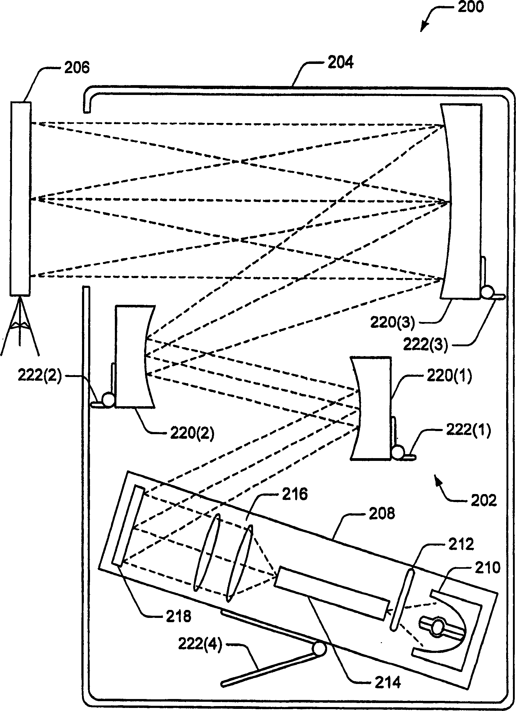
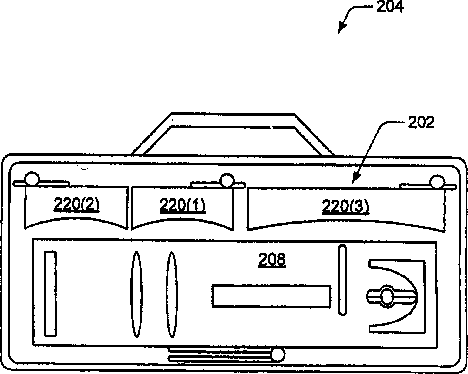
[0020] Described below are embodiments of light reflection systems. The described embodiment of the projection device is an imaging device comprising an illumination subsection and a light reflection system as projection light path. The illumination subsection includes a light source and various elements that form the illuminated image for projection. The light reflecting system consists of a light reflecting element that reflects and outputs an illuminated image for viewing. In one embodiment, the light reflecting system and the illuminating subsection can be converted from a working position to a transporting position by a foldable support structure that fixes the position of the reflecting element and the illuminating subsection.

[0021] Here, reference is generally made to various embodiments of a light reflecting system in an exemplary environment of a projection device. While some specific examples of reflective light systems may refer to particular implementations, s...


PUM


Abstract

In an implementation, a reflective optical assembly may be configured for translation from a portable position to an operational position. An image forming device may be configured to receive an input of an image and illumination input, provided by a light source, to generate an illuminated image output. The illuminated image output is reflected with the reflective optical assembly to direct the illuminated image output for display.

Description

technical field [0001] The present invention relates to a projection system and method, in particular to a portable projection system and method. Background technique [0002] Projection systems can be applied to many aspects of modern life and provide users with a wide range of functions. Projection systems may be implemented in projectors or other display devices capable of displaying images on a screen. Projection systems can also be used in rear projection TVs or home theaters. [0003] Projection systems, such as digital projectors, may have refractive glass optics in the projector's illumination and imaging systems. Glass optics are heavy, made of more expensive materials, and are more expensive to manufacture. In addition, refractive optical elements are prone to chromatic aberration due to the dispersion properties of refractive optical materials. Contents of the invention [0004] It is an object of the present invention to provide a portable projection system...

Claims


Application Information

Patent Timeline
IPC IPC(8): G02B5/10G02B17/00G02B17/06G03B21/00G03B21/14G03B21/20G03B21/28H04N5/74H04N9/31
CPCG02B17/0663H04N5/7408G03B21/20H04N9/3141G02B17/0642G03B21/28G03B21/30
Inventor M·A·帕特G·霍华德
Owner HEWLETT PACKARD DEV CO LP
Learn More