
Switchable combined grating structure

A grating structure, grating technology, applied in diffraction grating, optics, optical components and other directions, can solve problems such as single grating direction

Active Publication Date: 2018-10-09
北京中科维真科技有限公司
View PDF3 Cites 0 Cited by
  • Summary
  • Abstract
  • Description
  • Claims
  • Application Information

AI Technical Summary

Problems solved by technology

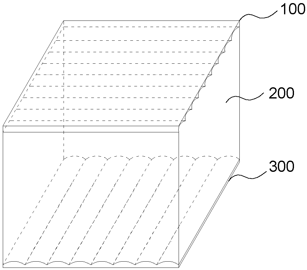
[0006] The purpose of the present invention is to solve the problem that the grating direction of the existing 2D / 3D switching products is single, and the 3D display screen can only be viewed in the horizontal or vertical direction, and provides a switchable combined grating structure

Method used


Image

  • Switchable combined grating structure
  • Switchable combined grating structure
  • Switchable combined grating structure

Examples


specific Embodiment approach 1

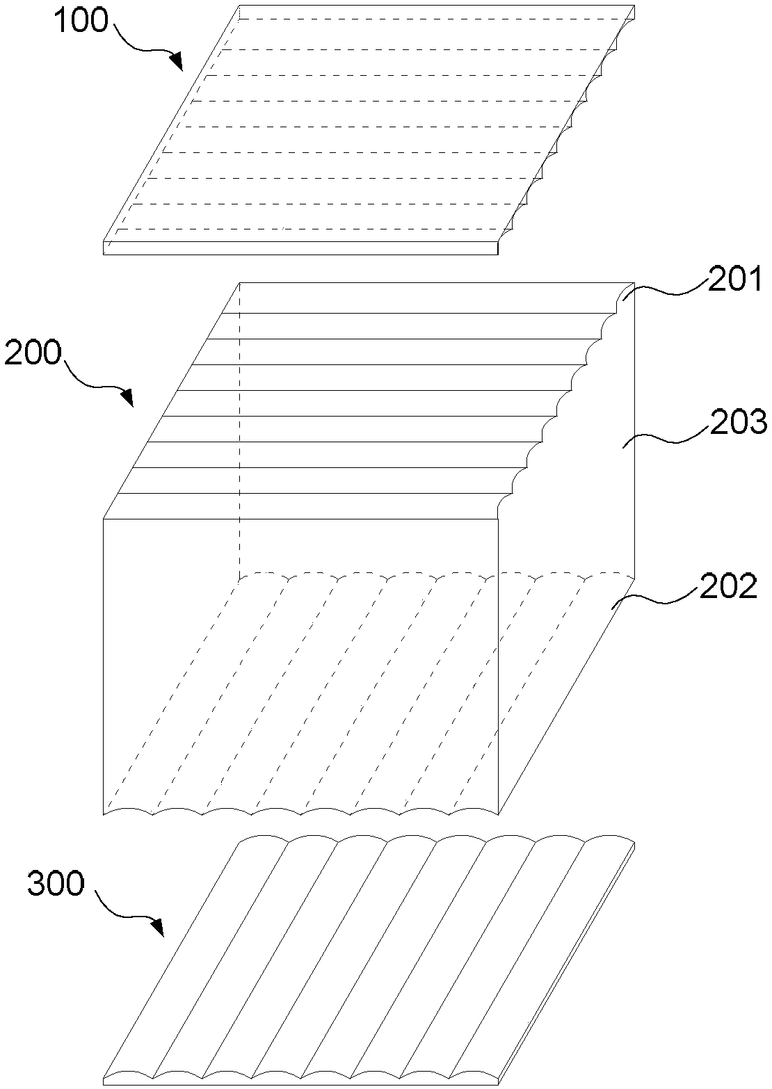
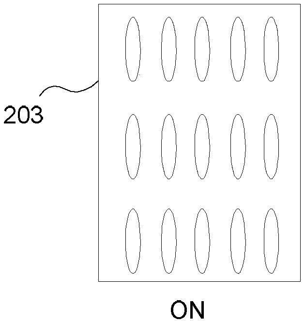
[0041] Specific implementation mode one: the following combination Figure 1 to Figure 4 , Figure 9 with Figure 10 Describe this embodiment mode. The switchable combined grating structure described in this embodiment mode is to switch between horizontal and vertical 3D display states, and the single-layer variable refractive index structure is sandwiched in the middle. By switching the single-layer variable refractive index structure 200, the , to realize the direction change of the grating film used for 3D display; the single-layer variable refractive index layer 200 is composed of an upper electrode 201 and a lower electrode 202, and a liquid crystal layer 203 sandwiched between them. When the upper and lower electrodes are energized, the liquid crystal layer 203 is ON state, see image 3 As shown, the expressed refractive index is ordinary light refractive index n o =n 3 At this time, it is shown that the low refractive index concave cylindrical lens grating 100, the ...

specific Embodiment approach 2

[0045] Specific implementation mode two: the following combination Figure 5 to Figure 10 Describe this embodiment mode. The switchable combined grating structure described in this embodiment mode is the switching between horizontal and vertical 3D display states, and 3D / 2D switching. The structure sandwiched in the middle is a multilayer variable refractive index structure. Different switching changes of the power structure 200 realize the direction change of the grating film for 3D / 2D display.

[0046] A specific embodiment is given, taking a 6-inch multi-parameter switching grating 3D mobile phone as an example, using a multi-layer variable refractive index layer structure.

[0047] The effective area of ​​the 6-inch screen is 74.52mm*132.48mm.

[0048] Its high refractive index convex cylindrical mirror grating 300 has a refractive index of n 3 =1.6, the refractive index of the low refractive index concave cylindrical mirror grating 100 is n 1 =1.45, m=2, that is, two-l...


PUM


Abstract

The invention discloses a switchable combined grating structure and belongs to the technical field of stereoscopic display, for solving the problems of complex structure and high cost of a conventional apparatus generating radial polarized light and angular polarized light. The switchable combined grating structure comprises a low-refractivity concave column lens grating, a high-refractivity convex column lens grating and a single-layer variable-refractivity structure, wherein the single-layer variable-refractivity structure is clamped between the low-refractivity concave column lens grating with refractivity of n1 and the high-refractivity convex column lens grating with refractivity of n3, and the single-layer variable-refractivity structure has ordinary light refractivity no and non-ordinary light refractivity ne and satisfies the following conditions no=n3, ne=n1 and n1<n3; the refractivity of the single-layer variable-refractivity structure at a power-on state is no, and the combined grating structure represents a 3D non-edge grating membrane in a horizontal direction; and the refractivity of the single-layer variable-refractivity structure at a power-off state is ne, and the combined grating structure represents a 3D non-edge grating membrane in a vertical direction.

Description

technical field [0001] The invention belongs to the technical field of stereoscopic display. Background technique [0002] The display device is a bridge connecting the colorful world and human vision. Human eyes can restore the real world through the display device. 2D display can only reflect a part of the real world, while the real, clear and intuitive display method is displayed through 3D stereoscopic display. At present, there are many ways to realize 3D display, among which the cylindrical lens grating naked-eye 3D display technology is currently a major mainstream technology. [0003] Cylindrical lens grating naked-eye 3D display technology uses the principle of spectroscopic refraction of the lens to project the rearranged multi-parallax stereoscopic images to the human eyes, so that the left and right eyes of the human can receive the parallax images at the same time, thereby producing a three-dimensional effect; cylindrical lens grating The structure of the cylin...

Claims


Application Information

Patent Timeline
Patent Type & Authority Patents(China)
IPC IPC(8): G02B5/18G02B27/22
CPCG02B5/1814G02B30/27
Inventor 张勇顾开宇魏厚伟
Owner 北京中科维真科技有限公司
Learn More