
Display device and mobile terminal

A display device and display panel technology, which is applied in the directions of instruments, calculations, character and pattern recognition, etc., can solve the problems of reducing the authenticity and integrity of fingerprint images, small fingerprint collection range, and difficult to collect fingerprints, etc., to achieve enhanced clarity and Accuracy, increased authenticity and integrity, increased range effects

Active Publication Date: 2021-08-03
GUANGZHOU GOVISIONOX TECH CO LTD
View PDF6 Cites 0 Cited by
  • Summary
  • Abstract
  • Description
  • Claims
  • Application Information

AI Technical Summary

Problems solved by technology

However, since this structure can only allow the light reflected by the center of the fingerprint to pass through the small hole, while the light reflected by the edge of the fingerprint is difficult to pass through the small hole, so it is difficult for the fingerprint module to collect edge information of the fingerprint, making the range of fingerprint collection small. Reduced authenticity and integrity of the fingerprint image

Method used


Image

  • Display device and mobile terminal
  • Display device and mobile terminal
  • Display device and mobile terminal

Examples


Embodiment 1

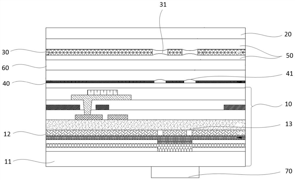
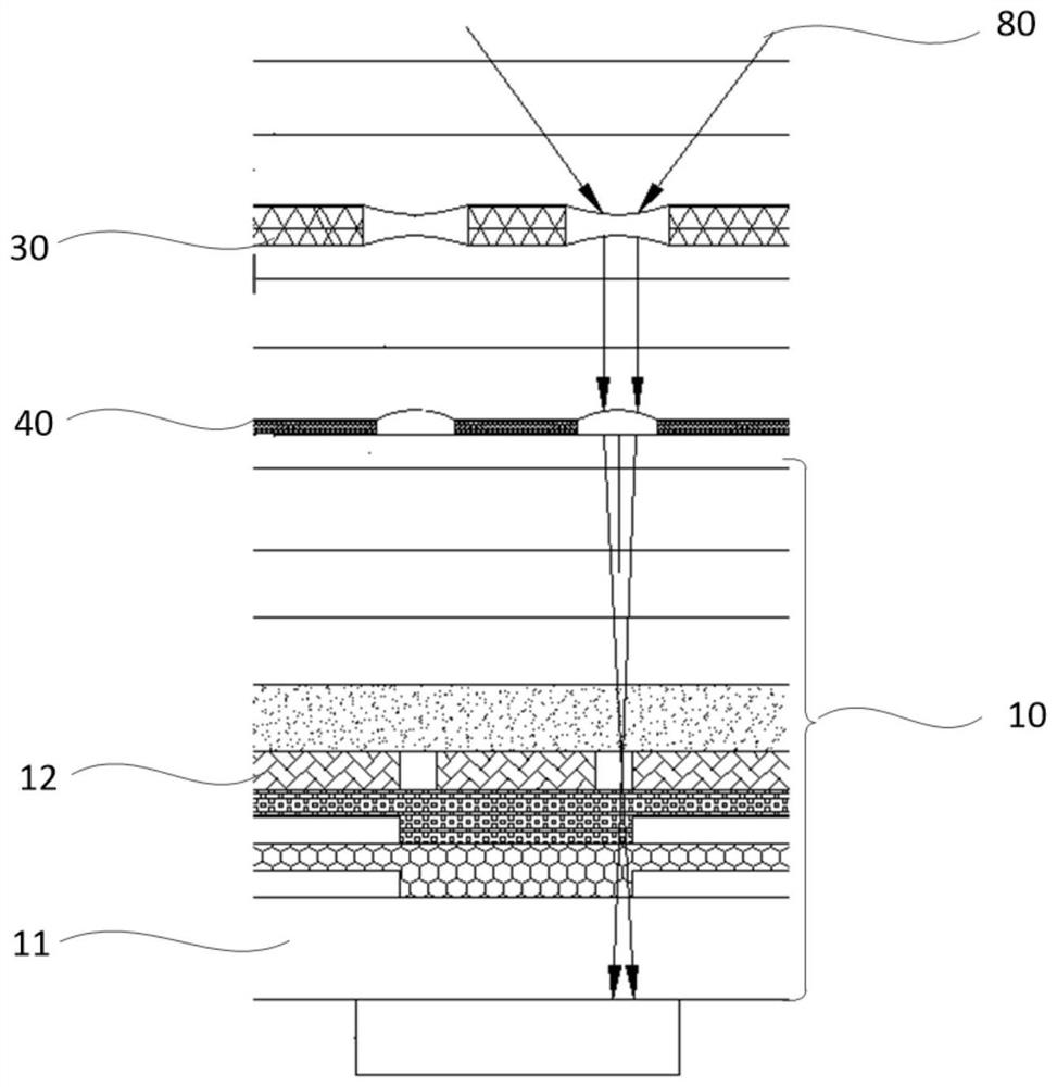
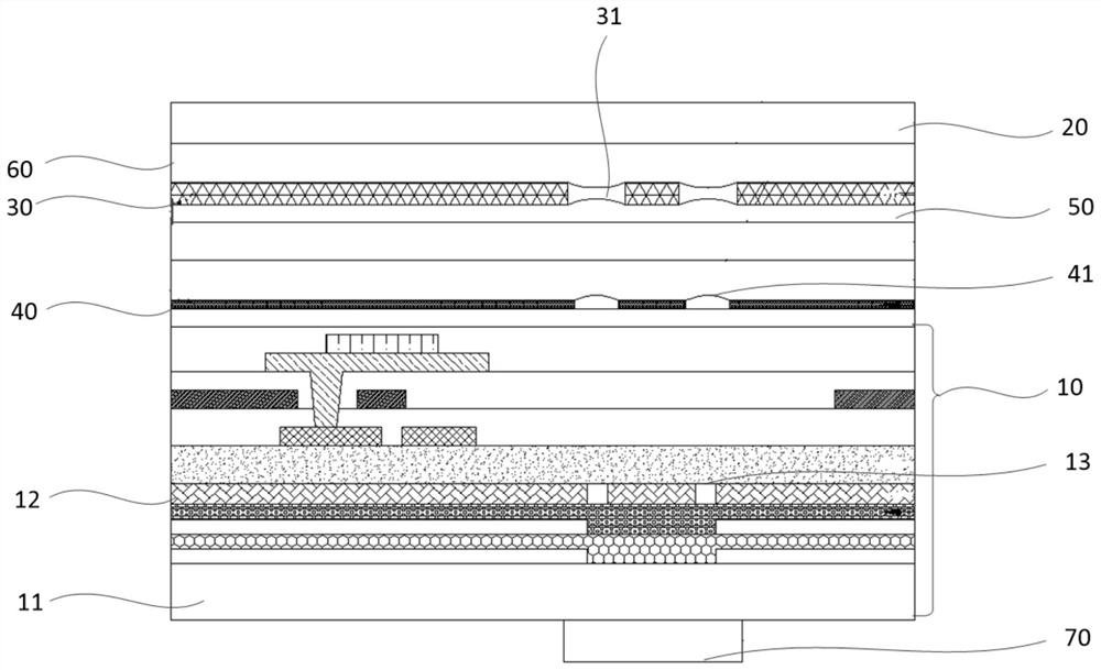
[0044] see figure 1 , figure 2 and Figure 4 , figure 1 Schematic diagram of the structure of the display device provided by Embodiment 1 of the present invention Figure 1 ; figure 2 for figure 1 Schematic diagram of light incidence in the display device. The display device provided by Embodiment 1 of the present invention includes a display panel 10 , a fingerprint module 70 arranged on the back of the display panel 10 , a cover 20 arranged on the front of the display panel 10 , and a cover 20 arranged between the cover 20 and the display panel 10 Concave lens film 30; the display panel 10 includes a matrix microhole array layer 12, a plurality of imaging through holes 13 are arranged in the matrix microhole array layer 12, and a convex lens film is arranged between the concave lens film 30 and the matrix microhole array layer 12 40, the distance between the concave lens film 30 and the convex lens film 40 is greater than the distance between the convex lens film 40 ...

Embodiment 2

[0061] The mobile terminal provided in Embodiment 2 of the present invention includes the display device provided in Embodiment 1 above. For the structure, function and implementation of the display device, reference may be made to the specific description in the above embodiment, and details will not be repeated here. The mobile terminal provided in this embodiment may be any device including a display device and having a display function, such as a mobile phone, a tablet computer, a smart watch, an e-book, a navigator, a TV, a digital camera, and the like. The mobile terminal provided in this embodiment also has the same advantages as the display device provided in Embodiment 1, which will not be repeated here.


PUM

PropertyMeasurementUnit
diameteraaaaaaaaaa

Abstract

The present invention provides a display device and a mobile terminal, wherein the display device includes a display panel, a fingerprint module, a cover plate, and a concave lens film arranged between the cover plate and the display panel; the display panel includes a matrix microhole array layer, a matrix A plurality of imaging through holes are arranged in the microhole array layer, and a convex lens film is arranged between the concave lens film and the matrix microhole array layer, and the distance between the concave lens film and the convex lens film is greater than the distance between the convex lens film and the matrix microhole array layer. The distance between them; the concave lens film includes a micro-concave lens array and a first light-shielding layer filled between adjacent micro-convex lenses, and the convex lens film includes a micro-convex lens array and a second light-shielding layer filled between adjacent micro-convex lenses; each micro The concave lens, each micro-convex lens and each imaging through hole are facing each other. By setting the concave lens film and the convex lens film in the display device, the incidence range of the reflected light of the fingerprint is enlarged, and the authenticity and integrity of the fingerprint image are improved.

Description

technical field [0001] The present invention relates to the field of display technology, in particular to a display device and a mobile terminal. Background technique [0002] In recent years, large-screen display devices have become more and more popular among consumers, and under-screen fingerprint technology can effectively increase the screen-to-body ratio under normal circumstances. The existing under-display fingerprint recognition usually adds an imaging through hole on the display panel, and uses the principle of small hole imaging to present a fingerprint image on the fingerprint sensor, thereby realizing the under-display fingerprint recognition. [0003] In the prior art, the display screen with the fingerprint recognition function under the screen usually has an imaging through hole on the thin film transistor layer or the source / drain electrode layer of the display panel, and uses the principle of small hole imaging to make the light reflected by the fingerprint...

Claims


Application Information

Patent Timeline
Patent Type & Authority Patents(China)
IPC IPC(8): G06K9/00
Inventor 杨超平袁强贾智帅梁珂
Owner GUANGZHOU GOVISIONOX TECH CO LTD
Learn More