

Ink jet head unit and ink jet recording apparatus mounted with the same
A technology of inkjet head and nozzle, which is applied in printing and other directions, can solve the problem of inkjet head unit becoming larger and achieve the effect of eliminating dead zone
- Summary
- Abstract
- Description
- Claims
- Application Information
AI Technical Summary
Problems solved by technology
Method used
Image

Examples
no. 1 example
[0058] The following will refer to Figures 37 to 40 An embodiment of the present invention is described. In these drawings, the same elements are denoted by the same reference numerals, and repeated descriptions are omitted.
[0059] Figure 37 is a perspective view showing an inkjet head unit according to an embodiment of the present invention, Figure 38 yes Figure 37 A side view of the inkjet head unit; Figure 39 yes Figure 37 A perspective view of the inkjet head unit of , showing the printhead and the flat cable being removed, and Figure 40 is showing Figure 39 Side view of the main part.
[0060] Figure 37 and 38 The inkjet head unit 1 shown in is mounted on an inkjet recording device (not shown) that ejects ink droplets from the head 2 by utilizing the piezoelectric effect of a dielectric thin film element, and makes the ink droplets collide with Recording is thus performed on a recording medium such as paper. The head 2 is composed of a film laminate ...
no. 2 example
[0076] The following will refer to Figures 1 to 1 0 describes an embodiment of the present invention. In these drawings, the same elements are denoted by the same reference numerals, and repeated descriptions are omitted.
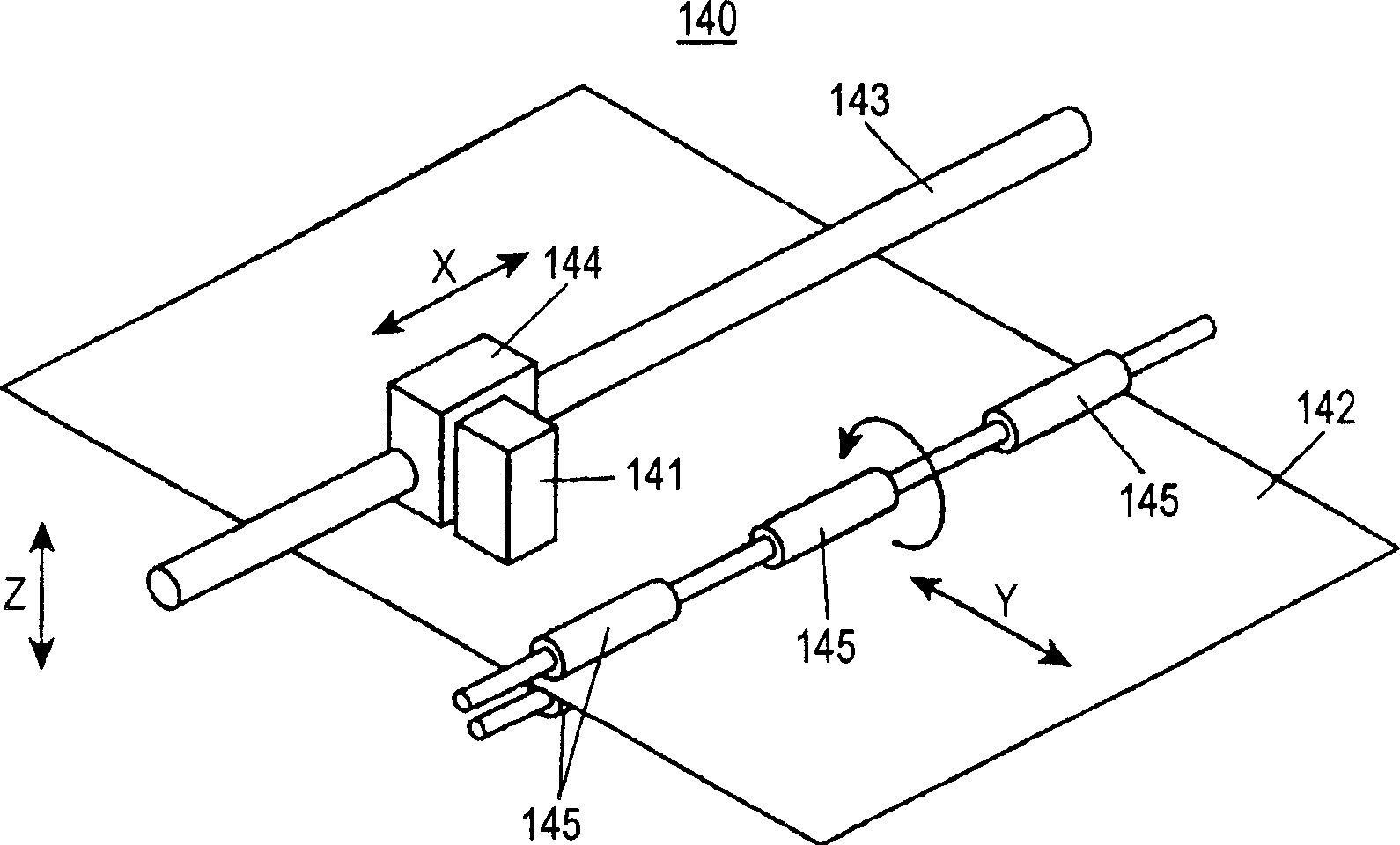
[0077] figure 1 The illustrated inkjet recording apparatus 140 is provided with an inkjet head 141 of the present invention, which performs recording by utilizing the piezoelectric effect of a piezoelectric element as an actuator, and makes the ink ejected from the inkjet head 141 The droplets impinge on a recording medium 142 such as paper, whereby recording is performed on the recording medium 142 . The inkjet head 141 is installed on the guide frame 144, wherein the guide frame 144 is arranged on the guide frame shaft 143 arranged along the main scanning direction, and the reciprocating movement of the inkjet head 141 along the guide frame shaft 143 corresponding to the guide frame 144 And it reciprocates along the main scanning direction X. Furthe...
no. 3 example
[0120] The following will refer to Figures 11 to 23 Embodiments of the present invention are described. In these drawings, the same elements are denoted by the same reference numerals, and repeated descriptions are omitted.
[0121] Figure 11 The inkjet recording device 240 shown has an inkjet head 241 that performs recording by utilizing the piezoelectric effect of a dielectric thin film element and the expansion force of air bubbles, and makes ink droplets ejected from the inkjet head 241 collide on a surface such as paper. on the recording medium 242, thereby performing recording on the recording medium 242.
[0122] In the case of constituting a line head by combining a plurality of nozzle heads, streaks appear in the printing at the junction between the nozzle heads due to uneven characteristics between the nozzle heads and the alignment accuracy of the nozzle head holders, resulting in poor print quality. reduce. Furthermore, in the case of combining a plurality of...
PUM
 Abstract
Description
Claims
Application Information