Signal generator

A signal generation and signal technology, applied in multiplexing communication, modulated carrier system, transmission system, etc., to achieve the effect of increasing power consumption, suppressing peak voltage, and suppressing peak value

Inactive Publication Date: 2011-02-09
KOKUSA ELECTRIC CO LTD
View PDF4 Cites 0 Cited by
  • Summary
  • Abstract
  • Description
  • Claims
  • Application Information

AI Technical Summary

Problems solved by technology

[0003] However, according to the methods disclosed in Patent Documents 1 to 4, a large amplifier with high power consumption is required, the signal frequency band after peak suppression becomes wider, and data errors Increase

Method used


Image

  • Signal generator
  • Signal generator
  • Signal generator

Examples


no. 1 Embodiment approach

[0065] Next, a first embodiment of the present invention will be described.

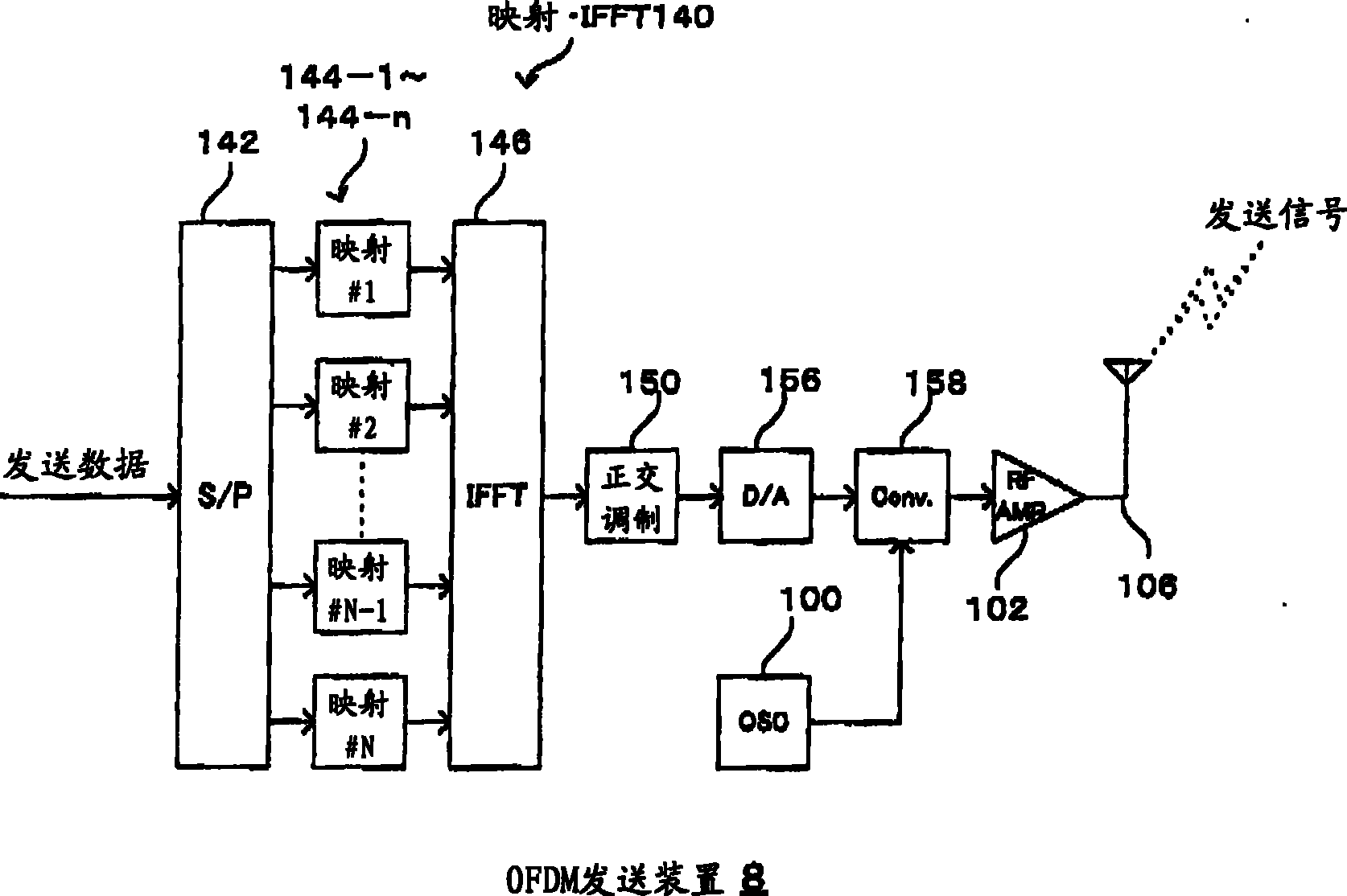
[0066] Figure 4 It is a configuration diagram showing the first OFDM transmission device 10 of the present invention.

[0067] Such as Figure 4 As shown, the first OFDM transmitting device 10 is composed of a mapping / IFFT unit 140, a local signal generating unit 100, RF-AMPs 102-1, 102-2, a combining unit 104, a transmitting antenna 106, a first transmitting signal generating unit 14 and a first The peak suppression unit 40 is configured.

[0068] The transmission signal generation unit 14 is composed of a quadrature modulation unit 150-1, a buffer unit 152, a subtraction unit 154, a D / A conversion unit 156-1, and a frequency conversion unit 158-1.

[0069] In addition, the peak suppression unit 40 is composed of a peak value / peak position (PV / PL) detection unit 400, a peak carrier (PC) extraction unit 410, a peak carrier generation unit 412, a quadrature modulation unit 150-2, and a D / A convers...

no. 2 Embodiment approach

[0117] Next, a second embodiment of the present invention will be described.

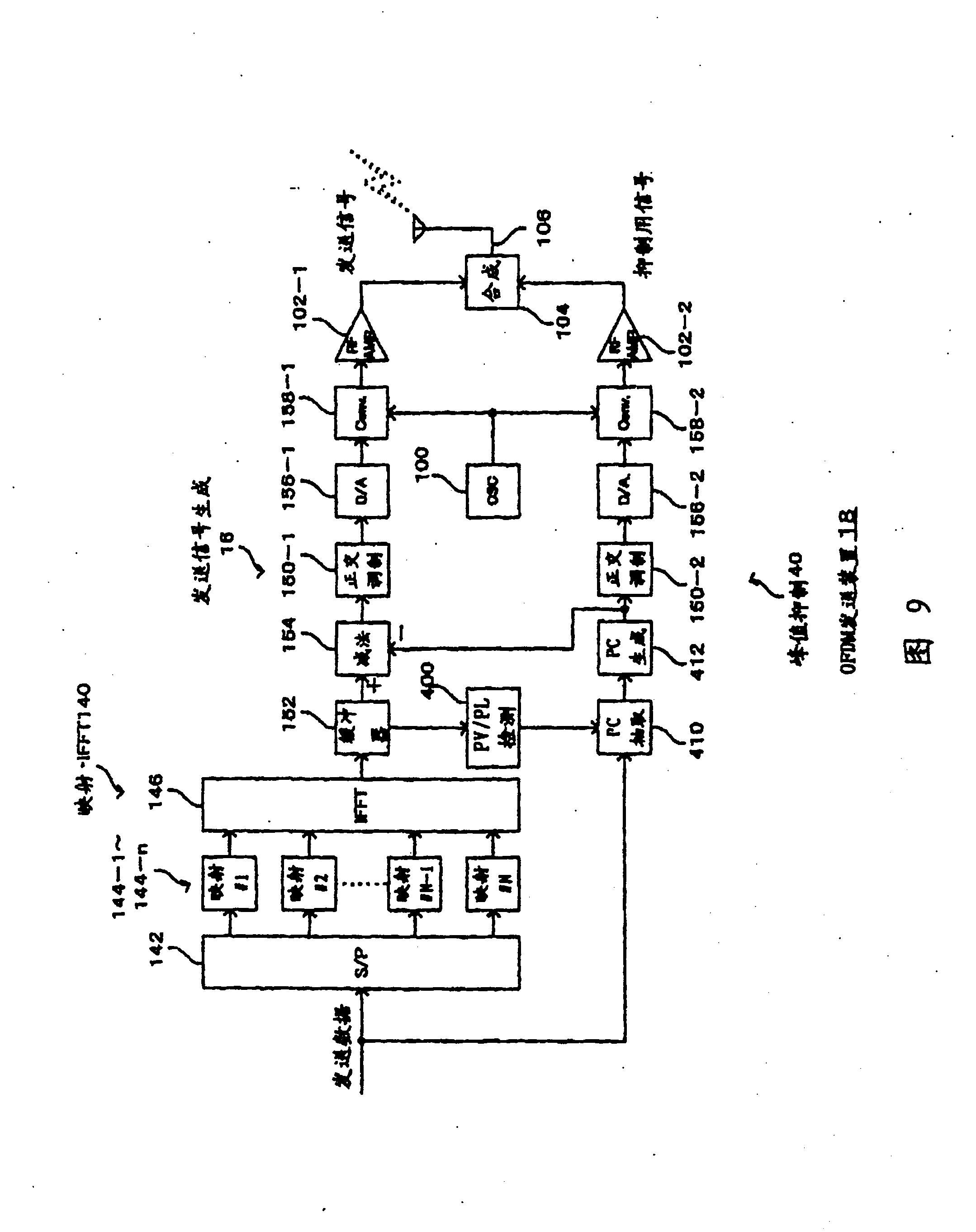
[0118] Figure 9 It is a diagram showing the configuration of the second OFDM transmission device 18 of the present invention.

[0119] Such as Figure 9 As shown, the second OFDM transmitting device 18 is composed of a mapping.IFFT part 140, a local signal generating part 100, RF-AMP102-1, 102-2, a combining part 104, a transmitting antenna 106, a second transmitting signal generating part 16 and a first The peak suppression unit 40 is configured.

[0120] Although the second transmission signal generation unit 16 includes the same as the first transmission signal generation unit 14 ( Figure 4 ) same structure, but there is a difference in the structure of both.

[0121] That is, in the first transmission signal generation unit 14, the quadrature modulation unit 150-1 exists between the mapping / IFFT unit 140 and the buffer unit 152, but in the second transmission signal generation unit 16, the...

no. 3 Embodiment approach

[0140] Next, a third embodiment of the present invention will be described.

[0141] Figure 11 It is a configuration diagram showing the third OFDM transmission device 20 of the present invention.

[0142] Such as Figure 11 As shown, the third OFDM sending device 20 adopts the following structure: remove Figure 4 Combining unit 104 and transmitting antenna 106 of first OFDM transmitting apparatus 10 shown in , are connected to directional transmitting antennas 110-1 and 110-2 on the respective output sides of RF-AMPs 102-1 and 102-2.

[0143] That is, the third OFDM transmitting apparatus 20 adopts a structure in which a transmission signal is sent from the directional transmission antenna 110-1, and a signal for peak suppression is sent from the directional transmission antenna 110-2, and the combining unit 104 is not used, and in the wireless communication line, the combined Send signal and signal for peak suppression.

[0144] For example, the directional transmittin...


PUM


Abstract

The present invention provided a signal generator capable of generating the signal of a multi-carrier system by effectively suppressing a peak without widening the band of the signal, generating a spurious signal, and increasing data errors. A peak value / peak position detector 400 detects a value and the position of the peak occurring in an amplitude of modulation data from an orthogonal modulator 150-1. A peak carrier extractor 410 extracts L number of sub-carriers minimizing the peak. A peak carrier generator 412 generates data for peak suppression corresponding to the extracted sub-carriers. A subtractor 154 subtracts the data for peak suppression from the modulation data. A transmitting signal generator 14 generates an analog transmitting signal from the modulation data. A peak suppressor 40 generates an analog signal for peak suppression from the data for peak suppression. A compositing part 104 composites the transmitting signal with the signal for peak suppression, and transmits it to a wireless communication line via a transmitting antenna 106.

Description

technical field [0001] The present invention relates to a signal generating device which generates a signal of a multi-carrier system with suppressed amplitude peaks. Background technique [0002] For example, Patent Documents 1 to 4 disclose methods for suppressing amplitude peaks that may occur in signals of a multi-carrier system such as OFDM (Orthogonal Frequency Division Multiplex). [0003] However, according to the methods disclosed in Patent Documents 1 to 4, a large amplifier with high power consumption is required, the signal bandwidth after peak suppression becomes wider, and data errors increase. [0004] Patent Document 1: Japanese Patent Application No. 2002-283460 [0005] Patent Document 2: Japanese Patent Application No. 2002-305489 [0006] Patent Document 3: JP-A-8-340361 [0007] Patent Document 4: Japanese Unexamined Patent Publication No. 7-143098 Contents of the invention [0008] The present invention has been made against the above-mentioned...

Claims


Application Information

Patent Timeline
Patent Type & Authority Patents(China)
IPC IPC(8): H04L27/04H04L27/26H04J11/00H04B1/04
CPCH04L27/262H04L27/2618
Inventor 内藤昌志
Owner KOKUSA ELECTRIC CO LTD
Why Eureka
Try Eureka