Drain socket and flush toilet

A toilet and flushing technology, which is applied in flushing toilets, water supply devices, buildings, etc., can solve problems such as pipe blockage, dirt is difficult to pass through, and siphoning is insufficient, so as to prevent dirt from clogging, reduce the contact area, The effect of reducing frictional resistance

A toilet and flushing technology, which is applied in flushing toilets, water supply devices, buildings, etc., can solve problems such as pipe blockage, dirt is difficult to pass through, and siphoning is insufficient, so as to prevent dirt from clogging, reduce the contact area, The effect of reducing frictional resistance

CN1714209AInactive Publication Date: 2005-12-28TOTO LTD

Image

  • Drain socket and flush toilet
  • Drain socket and flush toilet
  • Drain socket and flush toilet

Examples


Embodiment Construction

[0080] Hereinafter, embodiments of the present invention will be described based on the drawings.

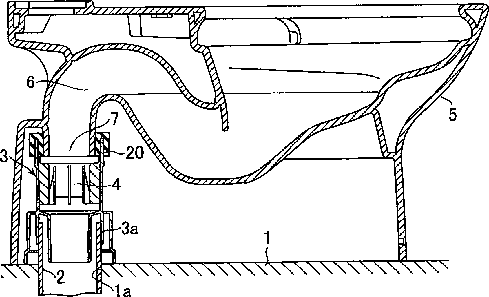
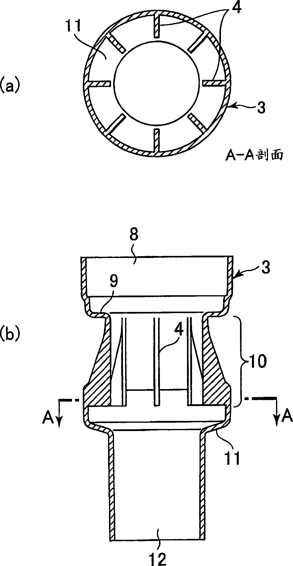
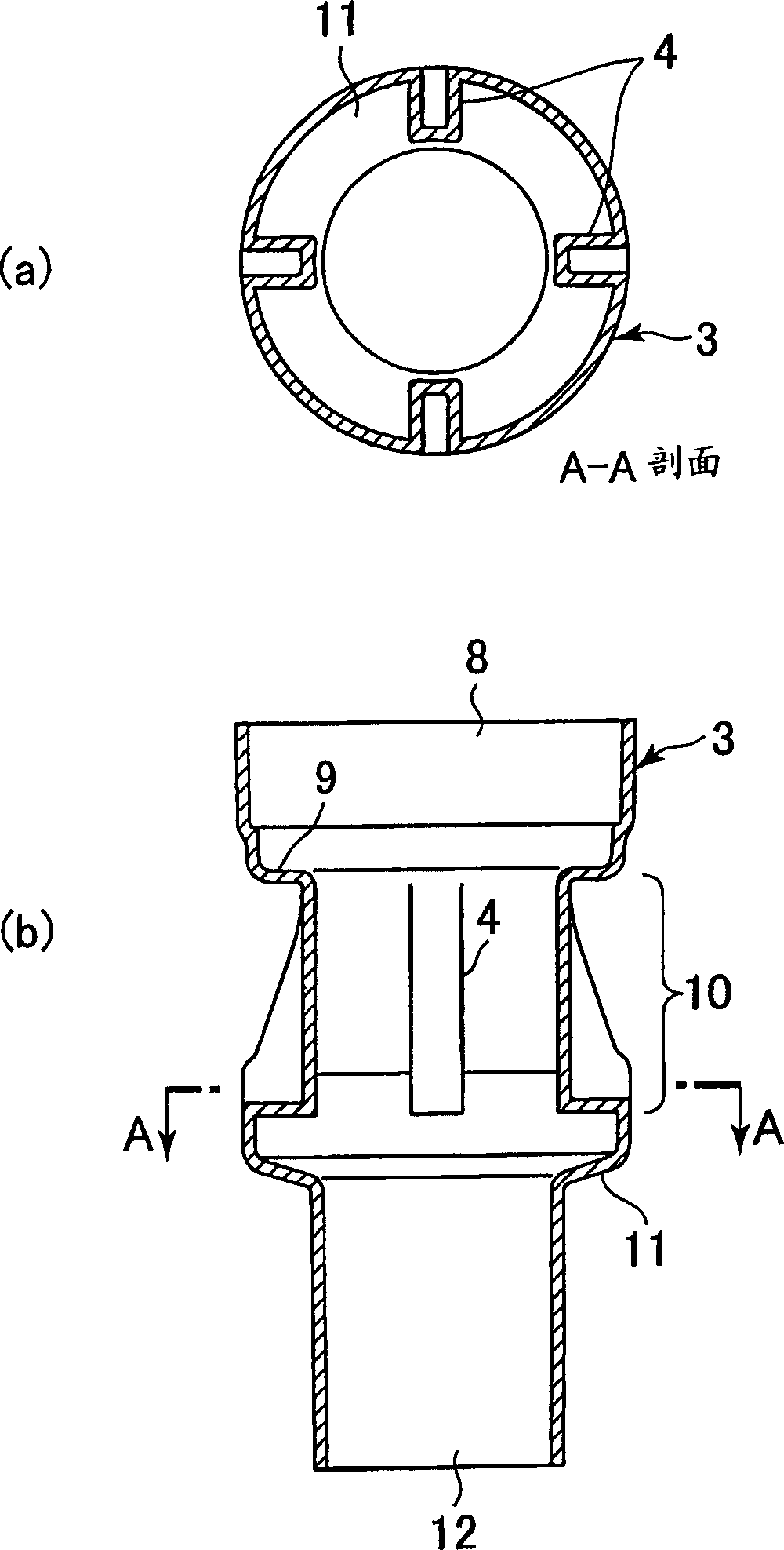
[0081] figure 1 It is a longitudinal sectional view showing the connection structure of the drain pedestal, the flush toilet body and the drainpipe according to the first embodiment of the present invention, figure 2 for will be with figure 1 It is an enlarged view of the main part cut off of the connection structure of the drain pipe of the drain seat part.

[0082] exist figure 1 Among them, the drain pipe 2 stands up from the hole 1a provided on the floor 1. On the drainpipe 2, a drain socket body 3 is watertightly fixed, and the drain socket body 3 is watertightly fixed to the outlet 7 of the elbow drainage channel 6 of the flush toilet body 5 installed on the floor 1. superior. In addition, the connection between the drain socket body 3 and the drain pipe 2 is performed through the connection portion 3a of the drain socket. A portion having a plurality of inner and o...


PUM


Abstract

The present invention provides a flush toilet or a drain pedestal that prevents clogging of pipes by aligning the direction of dirt passing through a drain trap without hindering the discharge capacity of drain by siphon action. The drain socket of the present invention is a drain socket that connects the outlet (7) of the elbow drainage channel of the flush toilet body (5) and the drain pipe (2) arranged outside the flush toilet body, and is characterized in that: It has: a drainage seat body (3) connected to the inlet of the elbow drainage road and the outlet connected to the drainage pipe; a siphon induction part arranged on the inner wall of the drainage seat body to induce the siphon effect (11); and a rectifying plate (4) extending from the inner wall surface toward the inner side of the flow path at the upstream of the siphon induction part of the drain socket body.

Description

technical field [0001] The present invention relates to an improvement of a drainage seat connected and arranged between the outlet of the elbow drainage path of the flush toilet to the end of the elbow drainage path of the flush toilet body and the drain pipe outside the toilet. Background technique [0002] Conventionally, as a method of improving the waste discharge performance of flush toilets, a siphon effect has been utilized. As this type of flush toilet, in order to induce siphon action, a side flow hole is formed on the outlet, and a necked drain seat is provided on the upstream side of the side flow hole (for example, refer to JP-A-8-260551). (pp. 2-4, figure 1 )). In this drain socket, a water film is formed by making the wash water turbulent through the constricted portion on the upstream side and the two stages of the side flow hole of the outflow port, so that the siphon effect occurs early. [0003] Moreover, this kind of drainage seat is made of the turbul...

Claims


Application Information

Patent Timeline
28 Dec 2005
Publication
CN1714209A
IPC
E03D11/16
Inventors
一木智康; 小关刚