Refrigeration storage warehouse

A technology for storage and refrigerant, which is applied to household refrigeration devices, defrosting, household appliances, etc. It can solve the problems of adverse effects on the cooling capacity of the storage room and the increase in the time required for defrosting, so as to promote the melting and refrigeration of frost. Ability deterioration suppression, effect of shortening time

Inactive Publication Date: 2006-01-04
SANYO ELECTRIC CO LTD
View PDF1 Cites 2 Cited by
  • Summary
  • Abstract
  • Description
  • Claims
  • Application Information

AI Technical Summary

Problems solved by technology

Therefore, frosting is most likely to grow on the outlet piping of the expansion valve. However, the frosting of the outlet piping of the expansion valve has not been considered in the past. During defrosting, residual frost occurs in the outlet piping. Significantly increased time, with the issue of detrimentally affecting the cooling capacity of storage rooms

Method used


Image

  • Refrigeration storage warehouse
  • Refrigeration storage warehouse
  • Refrigeration storage warehouse

Examples


Embodiment 1

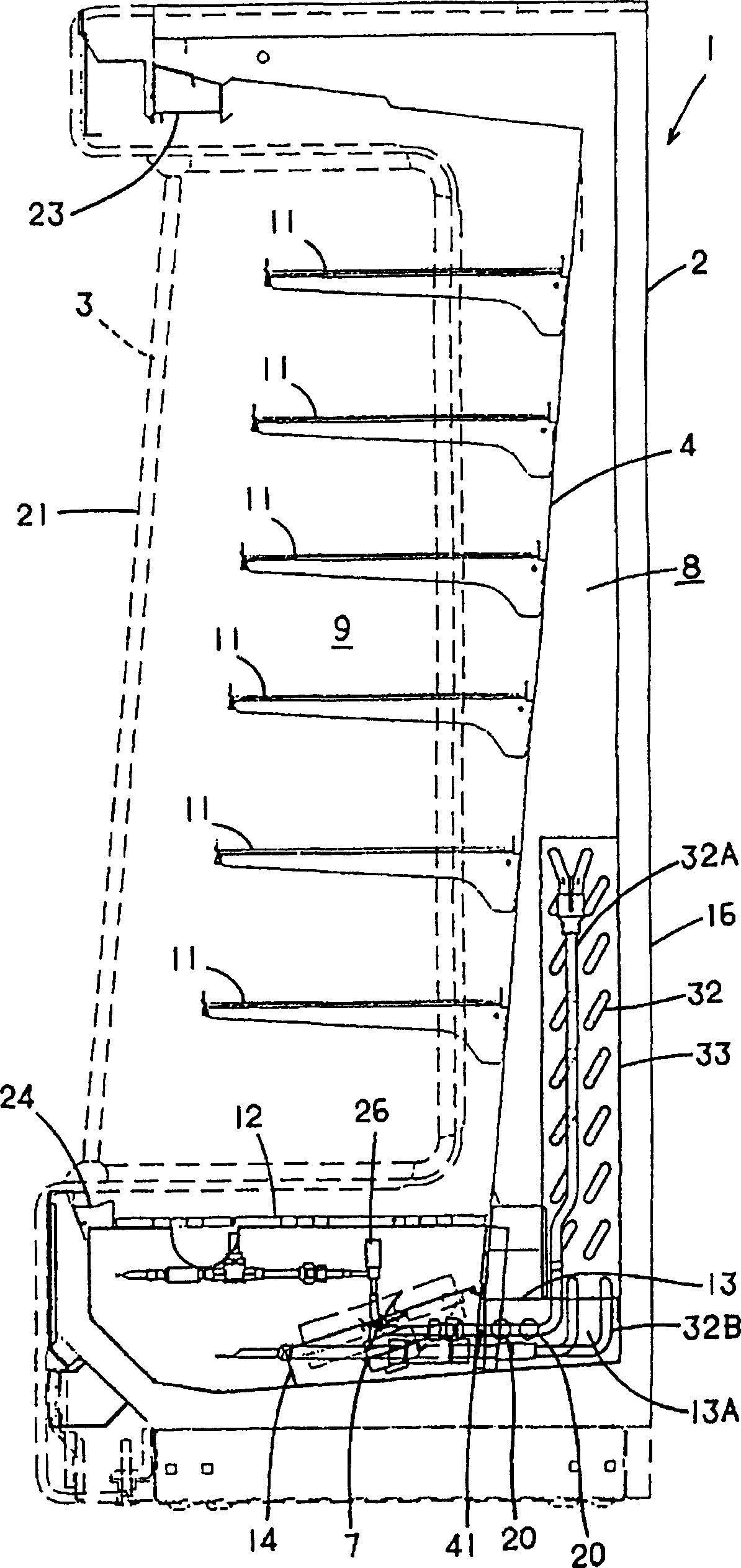
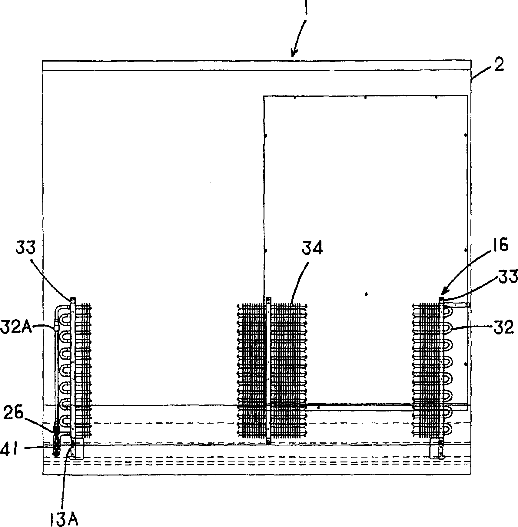
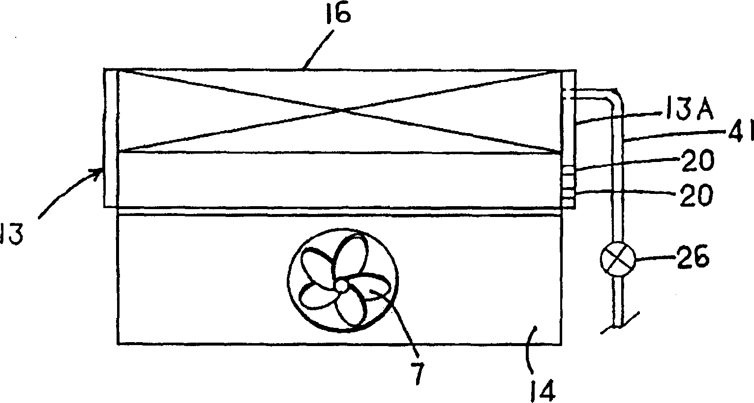
[0031] figure 1 It is a longitudinal sectional side view of a low-temperature showcase 1 as an embodiment of the refrigeration storage of the present invention; figure 2 is the perspective back view of the low temperature showcase 1; image 3 It is a plan view of the evaporator 16 part of the low temperature showcase 1. The low-temperature showcase 1 of the embodiment is a vertical open showcase installed in stores such as convenience stores and supermarkets. side panel 3. There is a space inside the heat insulating wall 2 and a partition 4 is installed. A pipe 8 is formed between the heat insulating wall 2 and the partition 4. The inside of the partition 4 forms a storage room 9 as a cooled space.

[0032] In this storage room 9, multi-layer shelves 11 are set up ..., and a pedestal 12 is installed at the bottom of the storage room 9 at the same time. An evaporator 16 constituting a refrigerant circuit of the refrigeration device is arranged vertically. Between the fan ...

Embodiment 2

[0047] Figure 4 represents another embodiment of the present invention. In this case, the outlet pipe 41 of the expansion valve 26 is introduced into the evaporator lower cover 13 (constituting a pipe) from the blowing side of the blower 7 to the evaporator 16 . Thus, by arranging the outlet pipe 41 in the duct from the outlet side of the blower 7 to the evaporator 16, the outlet pipe 41 of the expansion valve 26 is exposed to the wind from the blower 7, and the adhering frost can be effectively melted during defrosting.

Embodiment 3

[0049] Figure 5 Still another embodiment of the present invention is shown. In this case, an outlet pipe 41 of the expansion valve 26 is disposed on the upper air outflow side of the evaporator 16 . In this way, if the outlet pipe 41 is arranged on the air outflow side of the evaporator 16, the cold air dried through the evaporator 16 during cooling operation is blown onto the outlet pipe 41 of the expansion valve 26, and the adhesion of frost to the outlet pipe 41 can be suppressed. In addition, since the outlet pipe 41 of the expansion valve 26 is exposed to the wind from the blower 7 during the defrosting operation, it is possible to efficiently defrost the outlet pipe 41 where frost is most likely to adhere.


PUM


Abstract

To provide a cooling storage shed for effectively avoiding the extension of a defrosting time with frost formed on an outlet pipe of an expansion valve. In the cooling storage shed, refrigerant depressurized by an expansion valve 26 flows into an evaporator 16 for evaporation, and cold air heat-exchanged with the evaporator 16 is circulated into a storage chamber 9 via a duct 8 with a blower 7. The supply of the refrigerant to the evaporator 16 is stopped and the blower 7 is operated when defrosting the evaporator 16. Air discharged from the blower 7 hits the outlet pipe 41 of the expansion valve 26.

Description

technical field [0001] The present invention relates to a refrigerated storage such as a low temperature showcase and a refrigerator. Background technique [0002] In the past, in the low-temperature display cabinets installed in convenience stores and supermarkets, for example, a storage room for displaying goods was formed inside the heat-insulating wall and a duct was formed outside it, and an evaporator (refrigerator) and a blower were installed in the duct, and the blower was used. The cold air which has exchanged heat with this evaporator is circulated in the storage room (for example, refer patent document 1). [0003] At this time, the evaporator flows and evaporates the refrigerant decompressed by the expansion valve of the refrigeration circuit. Since the above-mentioned cooling operation frost grows on the evaporator, for example, the supply of refrigerant to the evaporator is periodically stopped, and only the blower is operated. The evaporator supplies air, whi...

Claims


Application Information

Patent Timeline
Patent Type & Authority Applications(China)
IPC IPC(8): F25D21/00F25D21/06
Inventor 针生聪小川太郎玉山弘司
Owner SANYO ELECTRIC CO LTD
Why Eureka
Try Eureka