Printed circuit board fixing structure of electronic product

A technology for printed circuit boards and fixed structures, which is applied in the directions of printed circuits, assembling printed circuits with electrical components, and manufacturing printed circuits to achieve the effect of reducing production costs and man-hours.

Inactive Publication Date: 2006-01-04
LG ELECTRONICS (TIANJIN) APPLIANCES CO LTD
View PDF0 Cites 8 Cited by
  • Summary
  • Abstract
  • Description
  • Claims
  • Application Information

AI Technical Summary

Problems solved by technology

[0013] As mentioned above, in the prior art, in order to fix the printed circuit board 20 on the control panel 10, the screw S which is another coupling means is required.

Method used


Image

  • Printed circuit board fixing structure of electronic product
  • Printed circuit board fixing structure of electronic product
  • Printed circuit board fixing structure of electronic product

Examples


Embodiment Construction

[0028] The printed circuit board fixing structure of the electronic product of the present invention will be described in detail below with reference to the accompanying drawings and embodiments.

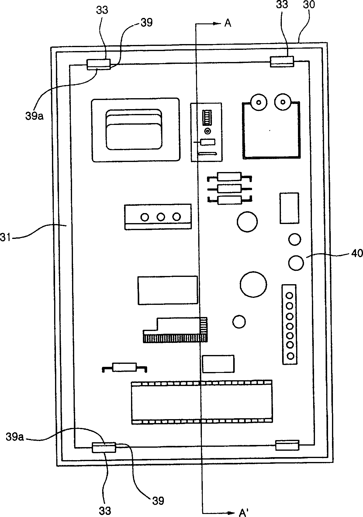
[0029] image 3 and Figure 4 It is a sectional view of an embodiment of the electronic product printed circuit board fixing structure of the present invention.

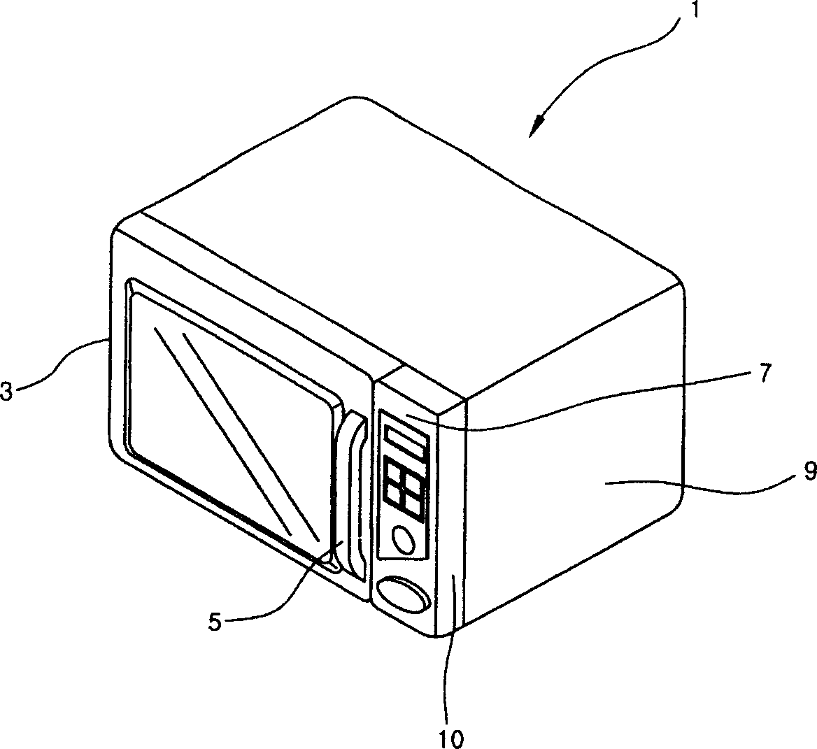
[0030] As shown in the figure, the control panel 30 forms the control section 7 of the microwave oven (refer to figure 1 ) appearance, and there is a predetermined installation space 31 inside the control panel 30 . In the installation space 31 is installed a printed circuit board 40 having various terminals for controlling the microwave oven.

[0031] A pair of fixing pieces 33 are provided at the upper and lower parts of the installation space 31 . The fixing pieces 33 are provided on the side surfaces facing each other, that is, on the long wall or the short wall, in order to fix the printed circuit board 40 .

[0...


PUM


Abstract

This invention provides a fixing structure of a PCB of an electronic product including PCB, a control panel and a pair of fixing plates, among which, a space for assembling the PCB is set inside of the back of the control panel, the flexible fixing plates are set at both sides of mutual opposite surfaces of the space to support the edge of the PCB. The result of this invention is that a PCB can be fixed by multiple fixing plates formed on the control panel, which can reduce numbers of fixing parts necessary for fixing the PCB and reduce the production cost.

Description

technical field [0001] The present invention relates to electronic products, in particular to a printed circuit board fixing structure for electronic products. Background technique [0002] A printed circuit board (PCB, printed circuit board) having various line terminals is used in electronic products, and the printed circuit board is mounted on a control portion of the electronic product. For the convenience of description, a microwave oven in an electronic product is taken as an example to illustrate the printed circuit board fixing structure. [0003] figure 1 It is a three-dimensional view of the appearance of a general microwave oven. [0004] As shown in the figure, an oven door 3 is provided on the front side of the body 1 of the microwave oven. The oven door 3 is for selectively opening and closing the cooking chamber (not shown) inside the body 1, and one end thereof is a central axis. The other end is rotatable forward and backward, and a door handle 5 is provi...

Claims


Application Information

Patent Timeline
Patent Type & Authority Applications(China)
IPC IPC(8): H05K3/36H05K3/00H05K13/04
Inventor 郑义秀
Owner LG ELECTRONICS (TIANJIN) APPLIANCES CO LTD
Why Eureka
Try Eureka