Curved needle drive device for sewing machine

A technology of a driving device and a sewing machine, which is applied to sewing machine components, sewing machine collar mechanisms, sewing equipment, etc., can solve the problems of troublesome processing of square sliders, troublesome adjustment of square sliders 51, proficiency, etc., and achieves simple and fast adjustment operations. Adjust the effect of the job

Active Publication Date: 2006-01-18
PEGASUS SEWING MACHINE MFG
View PDF2 Cites 3 Cited by
  • Summary
  • Abstract
  • Description
  • Claims
  • Application Information

AI Technical Summary

Problems solved by technology

[0010] However, in such a case, not only the tapering process of the sliding surface of the square slider 51 and the elongated hole 50a is troublesome i

Method used


Image

  • Curved needle drive device for sewing machine
  • Curved needle drive device for sewing machine
  • Curved needle drive device for sewing machine

Examples


Embodiment Construction

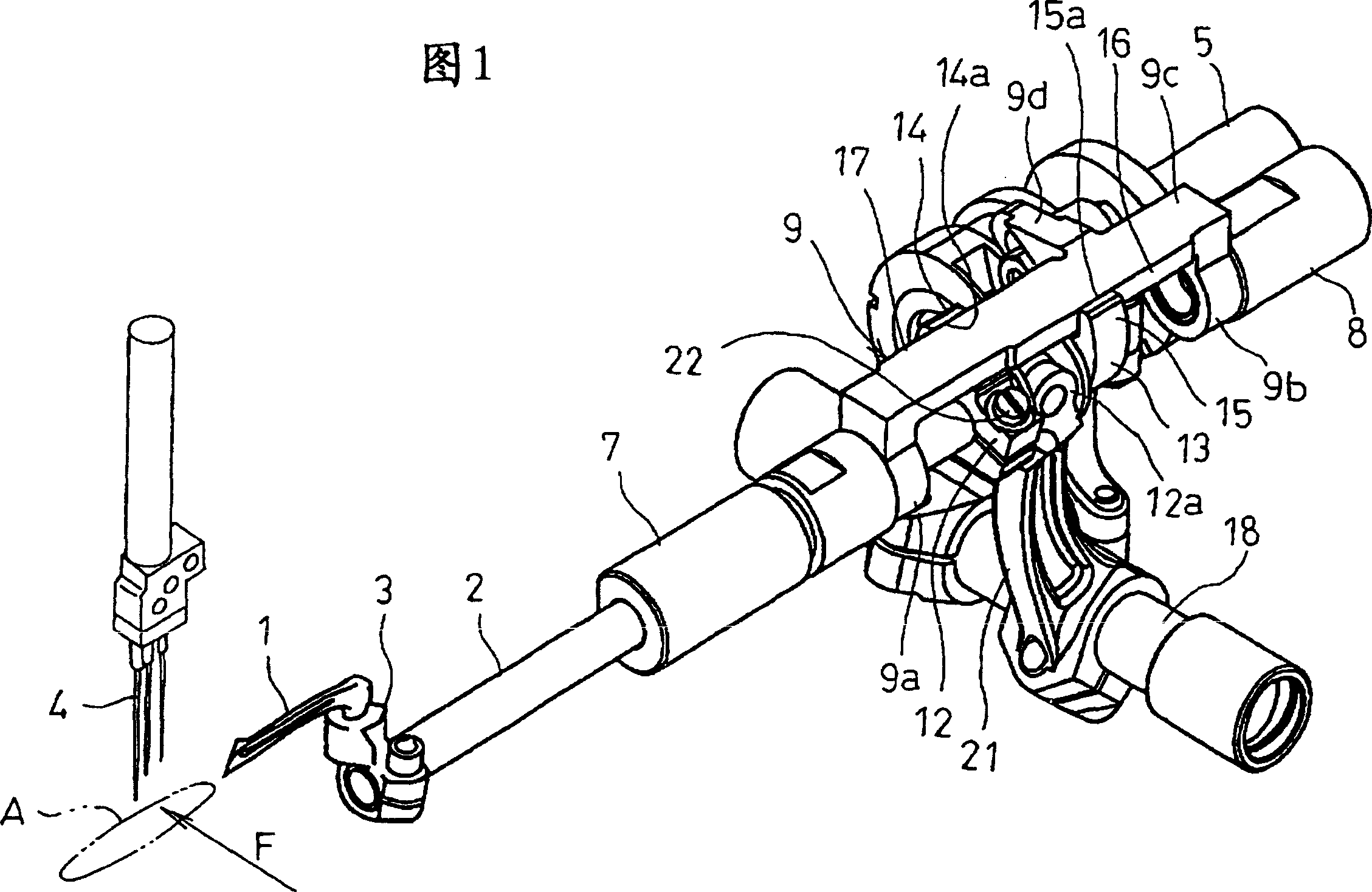
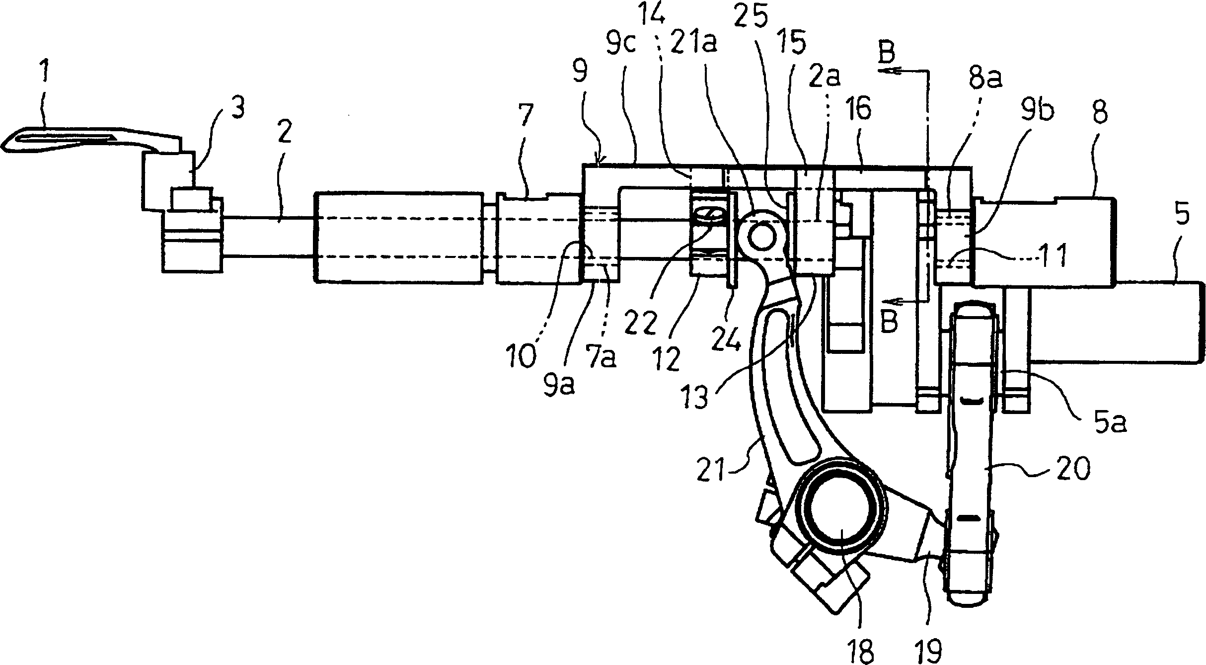
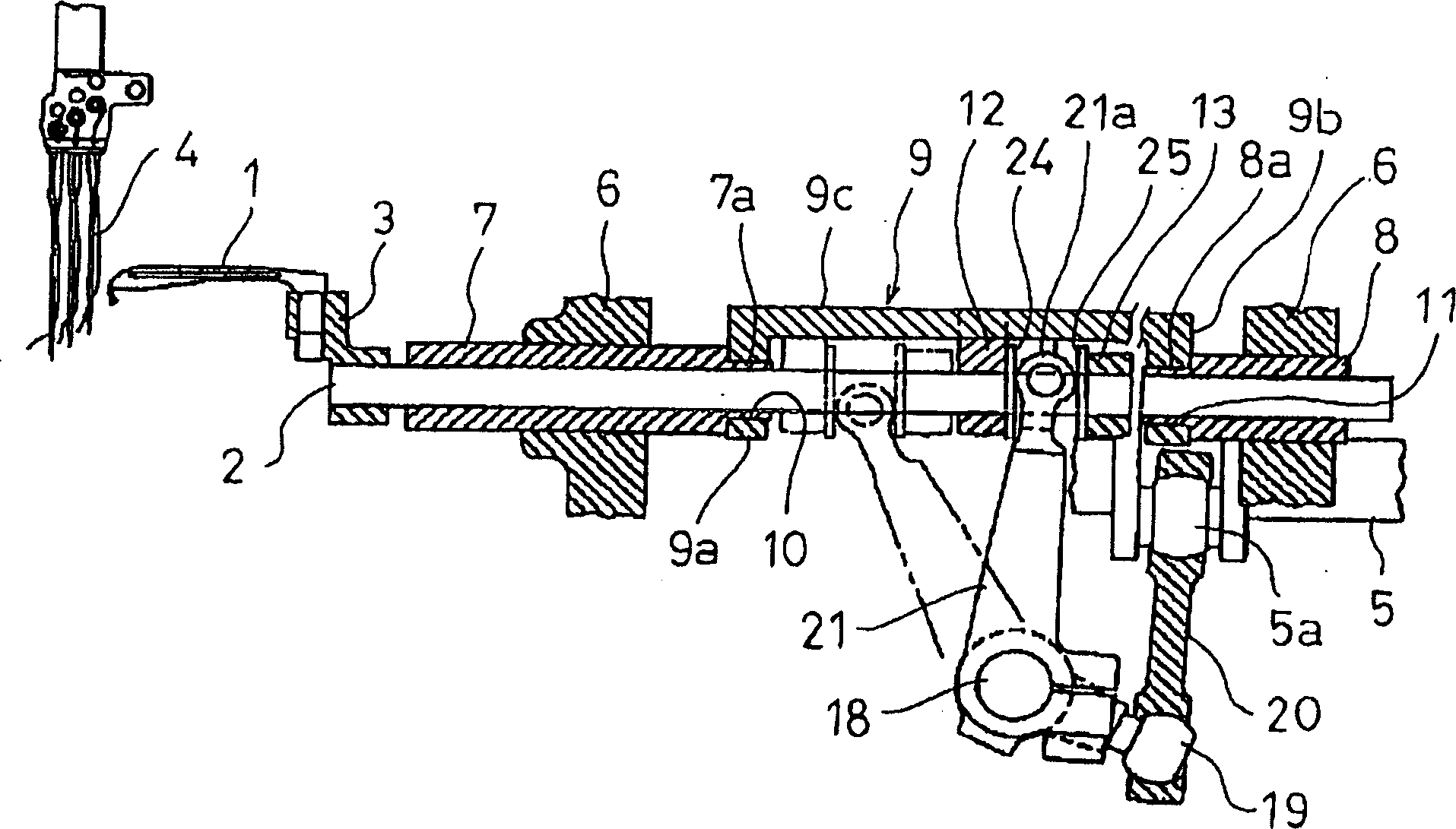
[0032] Preferred embodiments of the present invention are described below with reference to the accompanying drawings. Fig. 1 is a perspective view showing a looper driving device of a sewing machine according to an embodiment of the present invention, figure 2 It is the front view of the looper driving device of Fig. 1, image 3 It is a longitudinal sectional front view of the looper driving device of Fig. 1, Figure 4 It is a longitudinal sectional side view of the looper driving device of Fig. 1, Figure 5 for figure 2 Figure 6 is a perspective view of the main parts of the looper driving device of Figure 1 including the looper rod guide and the first and second cages, Figure 7 It is a perspective view of the first and second holders of the looper driving device in FIG. 1 .

[0033] Figure 1~ image 3 As shown, the looper 1 to be driven is attached to one end of the looper bar 2 via the looper stand 3 away from the axis of the looper bar 2 . The looper bar 2 is arran...


PUM


Abstract

To provide a looper drive for a sewing machine, by which adjusting work shifting to a suitable sliding state can be simplified even when a looper rod guide is worn attended with high speed operation, working of the looper rod guide can be simplified, and square pieces are omitted and man-hour of assembling work and the number of components can be reduced.In this looper drive for the sewing machine, a looper attached to one end of a looper rod 2 moves in a prescribed oblong orbit by synthetic motion of reciprocal movement in the axial direction by rocking of a rocking arm 21 and back and forth movement around the axis by a looper rod guide 9, a pair of first and second slide faces 16, 17 in parallel with the axial line direction of the looper rod 2 are set on the looper rod guide 9, and a first slide part 14 with a slide face 14a freely slidably abutting on the first slide face 16 is provided to one of first and second holders 12, 13 and a second slide part 15 with a slide face 15a slidably abutting on the second slide face 17 is provided to the other holder.

Description

technical field [0001] The present invention relates to a looper driving device for a sewing machine that operates synchronously with the vertical movement of the needle, such as a double-thread lockstitch sewing machine or a fancy stitch sewing machine. Background technique [0002] In the past, as the looper driving device of this sewing machine, for example, there are Figure 11 to Figure 15 A device as shown (for example, refer to Patent Documents 1 and 2). like Figure 11 , Figure 12 As shown, through the looper connecting rod 45 and the looper crank 44, the one-way rotation motion of the spherical crank portion 43a is converted into the swinging motion of the looper swing shaft 46 and the swing arm 47 installed on the looper swing shaft 46, The spherical crank portion 43 a is eccentric with respect to the axis of the main shaft 43 that rotates in synchronization with the vertical movement of the sewing machine needle 40 . The cylindrical portion 47a at the front en...

Claims


Application Information

Patent Timeline
IPC IPC(8): D05B57/36
CPCD05B57/02D05B57/32D05B61/00D05B63/00
Inventor 西川雅彦板东进
Owner PEGASUS SEWING MACHINE MFG
Why Eureka
Try Eureka