Transformation core and phase reversal transformation using the same

A technology of transformers and magnetic cores, applied in the direction of transformer/inductor magnetic cores, transformers, transformer/inductor components, etc., can solve the problems that the invention is difficult to realize, and achieve the effects of reducing the number of components, high efficiency, and reducing costs

Inactive Publication Date: 2006-02-01
TDK CORPARATION
View PDF2 Cites 0 Cited by
  • Summary
  • Abstract
  • Description
  • Claims
  • Application Information

AI Technical Summary

Problems solved by technology

However, the inventions involved in the above-mentioned patent documents are difficult to realize

Method used


Image

  • Transformation core and phase reversal transformation using the same
  • Transformation core and phase reversal transformation using the same
  • Transformation core and phase reversal transformation using the same

Examples


Embodiment Construction

[0035] The following describes the transformer core and the inverter transformer according to the present invention with reference to the accompanying drawings.

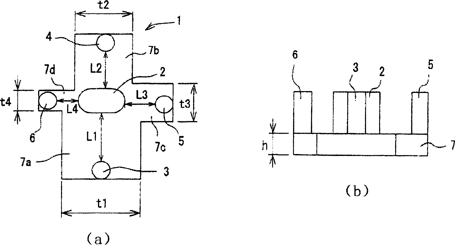
[0036] figure 1 (a) and (b) show an example of the transformer core (iron core) concerning this invention. In the iron core 1 of this embodiment, the primary coil leg 2 is arranged at the center, and three or more (here four are arranged) secondary coil legs 3, 4, 5, 6 are arranged around the periphery. The connecting plates 7 are magnetically combined.

[0037] These primary coil legs 2 , secondary coil legs 3 , 4 , 5 , 6 and connecting plate 7 are all made of ferrite material and integrated by sintering or other methods. As the ferrite material, any ferrite material such as Mn—Zn ferrite can be used. However, in order to improve performance, it is preferable to use ferrite materials with less iron loss, higher saturation magnetic flux density and excellent soft magnetic properties.

[0038] In this embodiment,...


PUM


Abstract

The present invention provides a magnetic core for transformer which can be formed in various shapes in accordance with the installed location and, in addition, from which outputs can be taken out uniformly, and to provide an inverter transformer. The magnetic core for transformer has a leg for primary coil around which a primary coil is wound and legs for secondary coil around which secondary coils are wound and which are magnetically connected to the leg for primary coil through connecting sections. A plurality of legs for secondary coil is arranged with respect to the leg for primary coil and, at the same time, the lengths of magnetic paths constituted of the legs for secondary coil are made different from each other. In addition, the differences among the magnetic resistances of the magnetic paths are reduced by adjusting at least partial cross-sectional areas or magnetic permeability of the magnetic paths in accordance with the lengths of the magnetic paths. To be concrete, the cross-sectional area (width) of the connecting section corresponding to the leg for secondary coil at the long distance from the leg for primary coil is made larger than the cross-sectional area (width) of the connecting section corresponding to the leg for secondary coil at the short distance from the leg for primary coil.

Description

technical field [0001] The present invention relates to a so-called multileg type transformer magnetic core in which a plurality of secondary coil legs are arranged corresponding to one primary coil leg, and an inverter transformer using the magnetic core. Background technique [0002] For example, in the backlight lighting circuit of the liquid crystal display device, the inverter transformer used to convert the voltage is generally connected by a pair of magnetic cores (ferrite cores) to form a closed magnetic circuit, and the iron cores are wound with different turns. Composed of a primary coil and a secondary coil. The basic shape of the iron core is representative of a U-shaped iron core with a pair of legs arranged at both ends of the connecting part, and an E-shaped iron core with a middle leg and a pair of outer legs symmetrically arranged on both sides connected through the connecting part. [0003] Figure 9 An example of an inverter transformer using a general U-...

Claims


Application Information

Patent Timeline
Patent Type & Authority Applications(China)
IPC IPC(8): H01F27/24H01F27/28H01F30/00
CPCH01F27/24H01F27/30H01F27/306
Inventor 伊藤信一郎
Owner TDK CORPARATION
Why Eureka
Try Eureka