Device and method for input/output circuit transformation from serial to parallel

An output circuit and circuit technology, applied in the field of input/output circuit devices, can solve the problems of insufficient IC output pins and slow speed.

Inactive Publication Date: 2006-02-08
VIA TECH INC
View PDF0 Cites 5 Cited by
  • Summary
  • Abstract
  • Description
  • Claims
  • Application Information

AI Technical Summary

Problems solved by technology

[0011] From the above, it can be found that the sequential logic circuit expands the output pin

Method used


Image

  • Device and method for input/output circuit transformation from serial to parallel
  • Device and method for input/output circuit transformation from serial to parallel
  • Device and method for input/output circuit transformation from serial to parallel

Examples


Embodiment Construction

[0054] The invention provides a device and method for converting an I / O circuit from serial to parallel, so that the I / O circuit can quickly output an input data stream without waiting. A preferred embodiment will be listed below. However, those skilled in the art know that this is only an example and is not intended to limit the invention itself. The preferred embodiments of this invention are described in detail below.

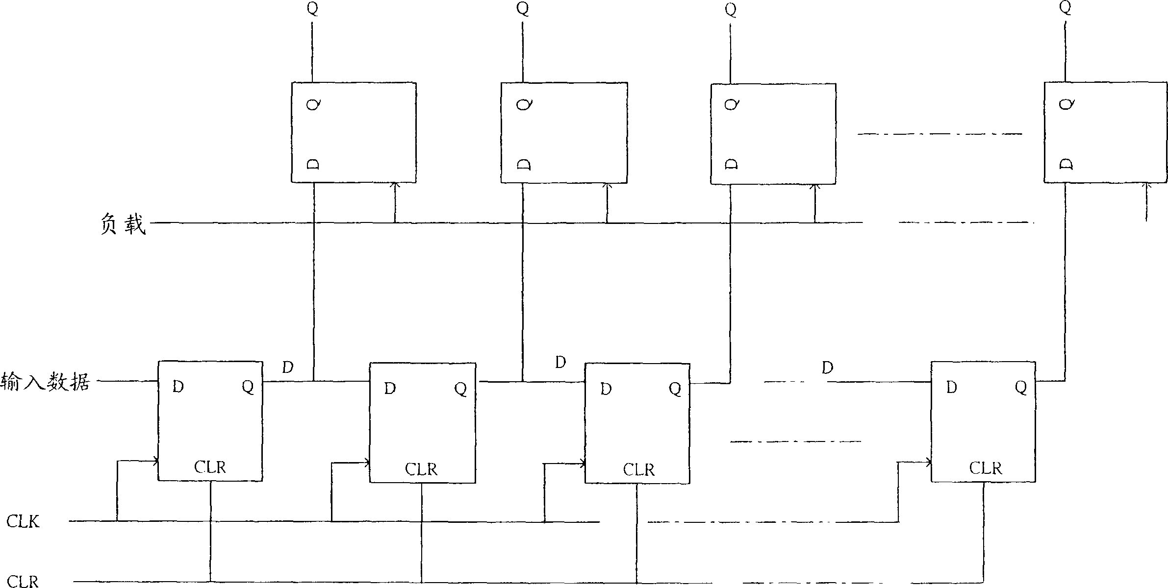
[0055] Figure 4A I / O circuit serial to parallel device 400 representing a preferred embodiment of the present invention, Figure 4B Means Figure 4A The detailed structure diagram. Figure 4B The circuit shown includes: M sequential logic circuits SL (SL 0 , SL 1 ,..., SL M-1 ); Each sequential logic circuit includes: a first D flip-flop D 1 (D 10 , D 11 ,..., D 1M-1 ) To receive 1-bit input data. In addition, the output of each first D flip-flop is connected to the input of the next first D flip-flop (for example: the first first D flip-flop D 10 The output i...


PUM


Abstract

Disclosed is apparatus for converting serial to parallel I/O, which comprises: M sequential logic circuits. The sequential logic circuit comprises: a first D trigger for receiving a bit of inputting data, every first D trigger output is connected with the input of next first D trigger; a second D trigger for receiving a bit start control signal and its output is connected to the input of next D trigger; a polyplexer with two inputs for receiving the input data the first D trigger received and a start control signal receiving end for receiving the start control signal the second D trigger received; a D type gating latch for outputting data that are fed back to the other input end of the polyplexer.

Description

Technical field [0001] The present invention relates to an input / output (I / O) circuit device and method, in particular to a serial to parallel (serial to parallel) device and method in an I / O circuit. Background technique [0002] Generally, after the manufacture of an integrated circuit (IC) is completed, the number of pins (pin) is also fixed, and at the same time due to the system on a chip (SOC: system on a chip) trend, some pins must be shared. In order to achieve the purpose of reducing IC size. Therefore, with limited pins and the trend of SOC, the multifunction of a single pin is an inevitable result. [0003] Such as figure 1 As shown, one pin of an IC designed with a single-pin multi-function concept can have many functions at the same time, but only one function can exist at the same time (that is, only one of the functions can be selected at the same time To use this pin), in this case, you must wait until this function is completed before switching to the next funct...

Claims


Application Information

Patent Timeline
IPC IPC(8): H03M9/00
Inventor 李政道
Owner VIA TECH INC
Why Eureka
Try Eureka