
Shroud and blower using the same

A technology of blower and shield, applied in the field of axial flow blower

Inactive Publication Date: 2006-02-15
DENSO CORP
View PDF1 Cites 6 Cited by
  • Summary
  • Abstract
  • Description
  • Claims
  • Application Information

AI Technical Summary

Problems solved by technology

This structure is effective for reducing the rotational noise (second and fourth noise components) in the second and fourth frequency ranges, but is ineffective for reducing the rotational noise (first noise component) in the first frequency range

Method used


Image

  • Shroud and blower using the same
  • Shroud and blower using the same
  • Shroud and blower using the same

Examples


Embodiment Construction

[0019] Preferred embodiments of the present invention will be described herein with reference to the accompanying drawings.

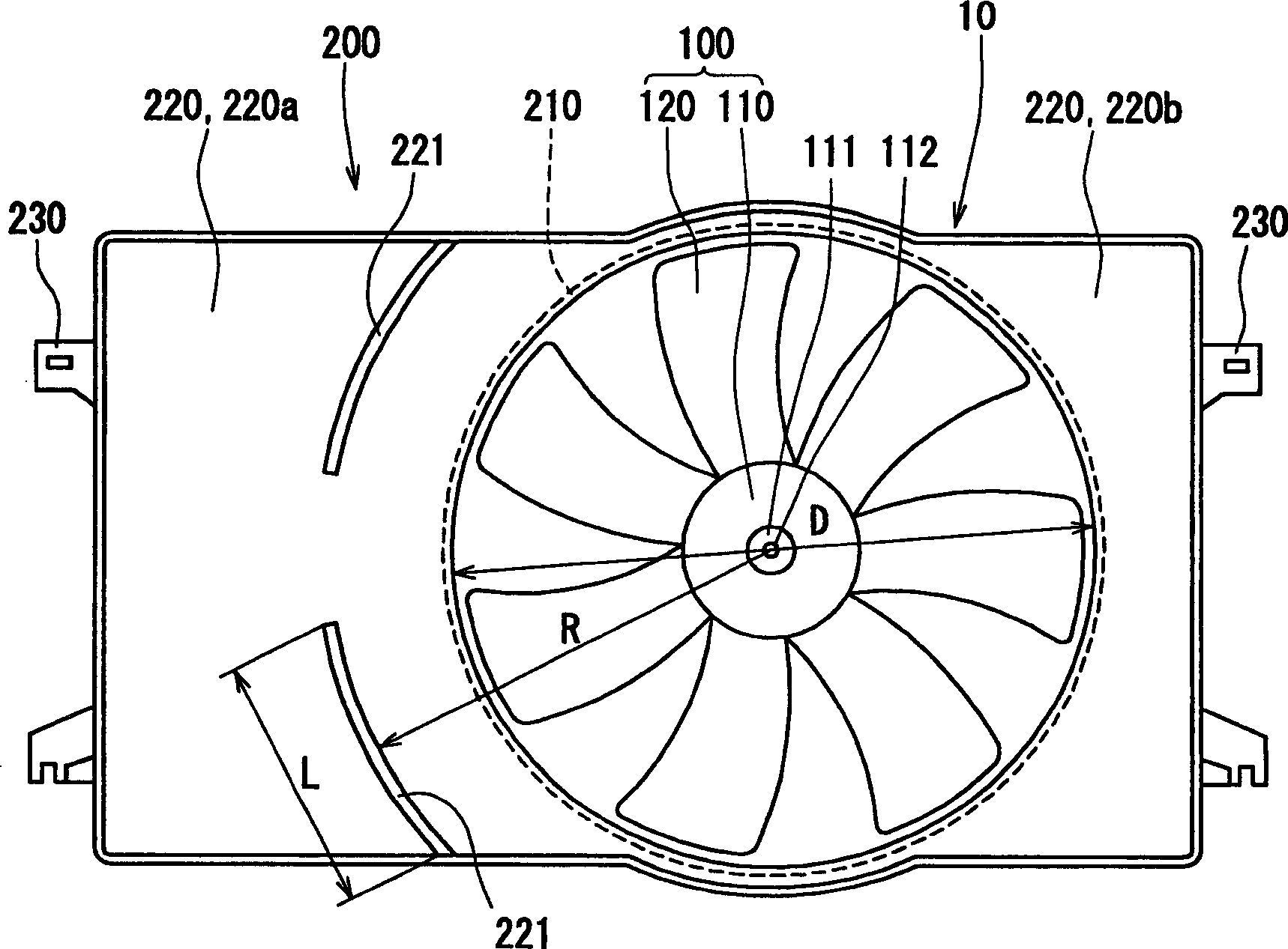
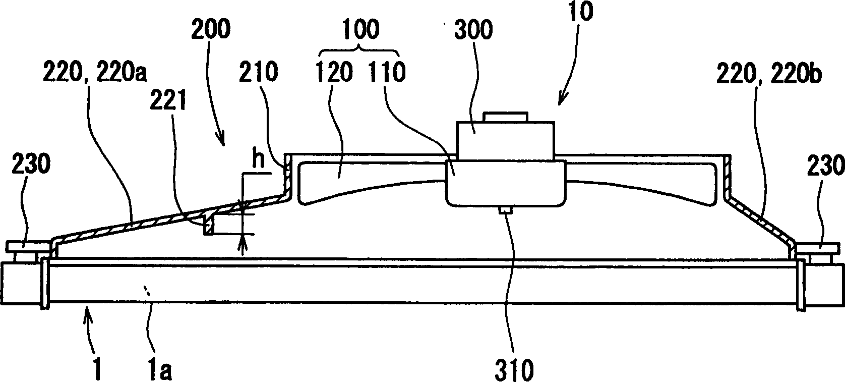
[0020] In this embodiment, the shroud 200 of the present invention is used in the axial blower 10 (electric fan) of the radiator (heat exchanger) 1 . The axial blower 10 is formed by assembling an axial fan 100 and a motor 300 . Figure 1A with 1B The structure of the axial blower 10 is shown.

[0021] The axial blower 10 (hereinafter referred to as the blower 10 ) is fixed on the radiator 1 on the engine side of the vehicle through the mounting elements 230 on the four corners of the shroud 200 . The blower 10 sends cool air to the central portion 1a of the radiator 1. As shown in FIG. The blower 10 is an air suction blower 10 that sucks air from the vehicle grill side to the engine side, that is, from the center portion 1 a of the radiator 1 to the axial fan 100 .

[0022] The axial flow fan 100 (hereinafter referred to as the fan) is made of polyp...


PUM


Abstract

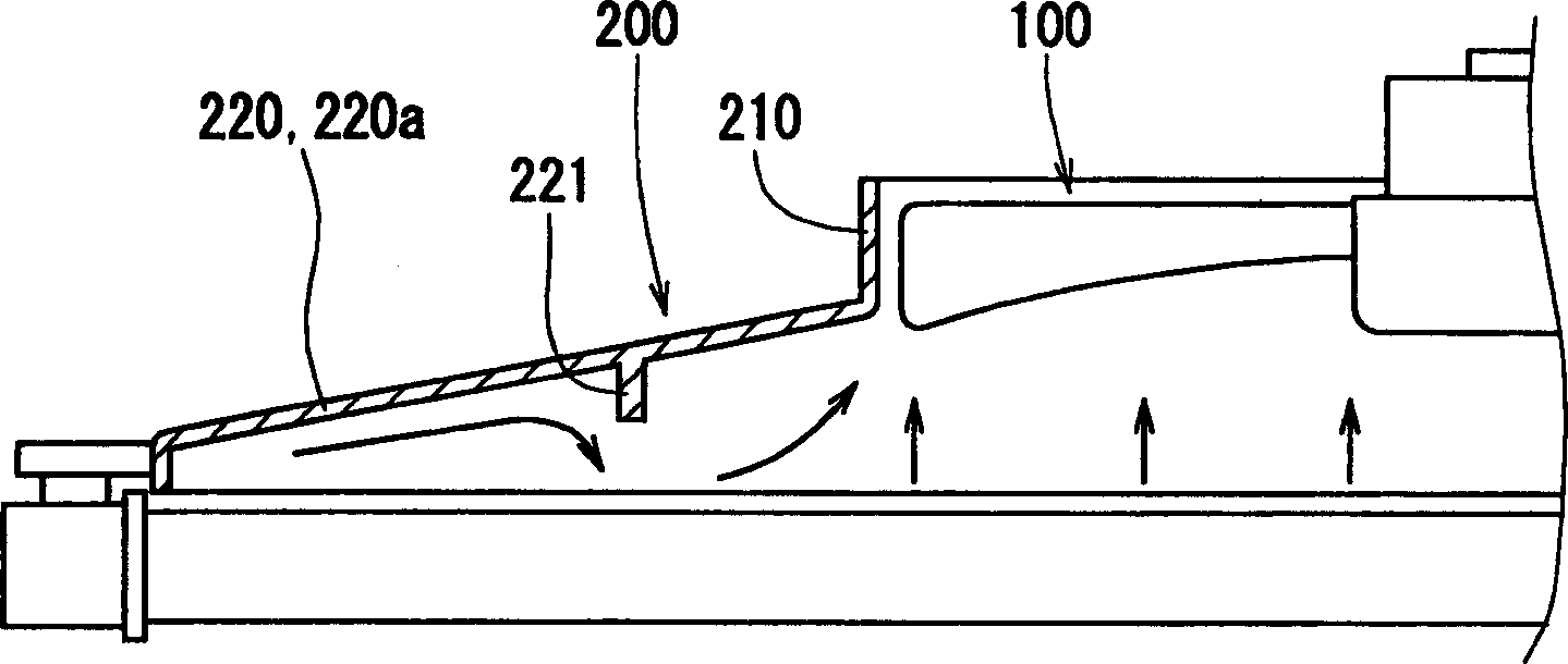
A shroud includes a ring portion (210) surrounding a radial outer rim of an axial flow fan (100) for blowing air, and an air introducing part (220), for introducing air to the ring portion (210), enlarged from the ring portion (210) towards upstream in the airflow. The fan is located opposite to a heat exchanger (1) positioned upstream of the fan (100) in the airflow, and a center of the ring portion (210) is eccentric with respect to a center of the air introducing part (220). In the shroud, an airflow regulating plate (221) protrudes toward an upstream side of the airflow and forms a circular arc shape concentric with the ring portion (210) within a larger-area part (220a) of the air introducing part (220), which is formed due to the eccentrically located ring portion (210). Therefore, the first noise component of fan rotation noise can be effectively reduced without reducing an air amount passing through a heat exchanger.

Description

technical field [0001] The present invention relates to a shroud and an axial blower using the shroud, which are suitable for use, for example, in a radiator of a vehicle. More particularly, the present invention relates to a shroud having an air flow regulating plate which effectively reduces noise generated by an axial fan. Background technique [0002] As a shroud for an axial blower for a heat exchanger, a shroud described in JP-A-6-42498 is known. In this shroud, since the center of the axial flow fan is arranged eccentrically with respect to the heat exchanger, an opening is provided in a part of the small area of ​​the air introduction portion of the shroud on the upstream side of the axial flow fan . [0003] Generally speaking, when the center of the axial fan is eccentric with respect to the heat exchanger, the rotational noise of the axial fan, especially the noise in the first frequency range (the first noise component) becomes very noticeable. In such a shrou...

Claims


Application Information

Patent Timeline
Patent Type & Authority Applications(China)
IPC IPC(8): F01P11/10F04D19/00
CPCF04D29/667F04D29/541
Inventor 桥本笃德鹰羽浩孝
Owner DENSO CORP
Learn More