Counter-rotating fan

A technology of rotary fan and rotation axis, which is applied in the field of fan equipment, can solve the problems of change of inflow attack angle, periodic pulsation of pressure distribution on the surface of the second-stage blade, loud noise, etc., and achieve the effect of improving efficiency

Pending Publication Date: 2020-04-21
GUANGDONG MIDEA WHITE HOME APPLIANCE TECH INNOVATION CENT CO LTD +1
View PDF0 Cites 3 Cited by
  • Summary
  • Abstract
  • Description
  • Claims
  • Application Information

AI Technical Summary

Problems solved by technology

[0004] 1) In the related art, because the angle between the front and rear blades of the counter-rotating fan is 0, although the front and rear blades rotate in different directions, they still overlap periodically, and the trailing edge of the blades of the previous blades flows out The loss flow field of the second-stage blade will pass through the leading edge of the second-stage blade, resulting in a change in the inflow angle of attack, which will cause periodic fluctuations in the pressure distribution of the second-stage blade surface, which will cause greater noise
[0005] 2) In the related art, when the front and rear two-stage blades of the counter-rotating fan overlap, the loss flow field flowing out of the trailing edge of the previous stage blade will pass through the leading edge of the latter stage blade, resulting in a change in the inflow angle of attack, thereby reducing the flow rate of the latter stage. Aerodynamic performance of the blade
This part of the speed cannot be used in open fan products, and the resulting radial energy loss is considerable

Method used


Image

  • Counter-rotating fan
  • Counter-rotating fan
  • Counter-rotating fan

Examples


Embodiment

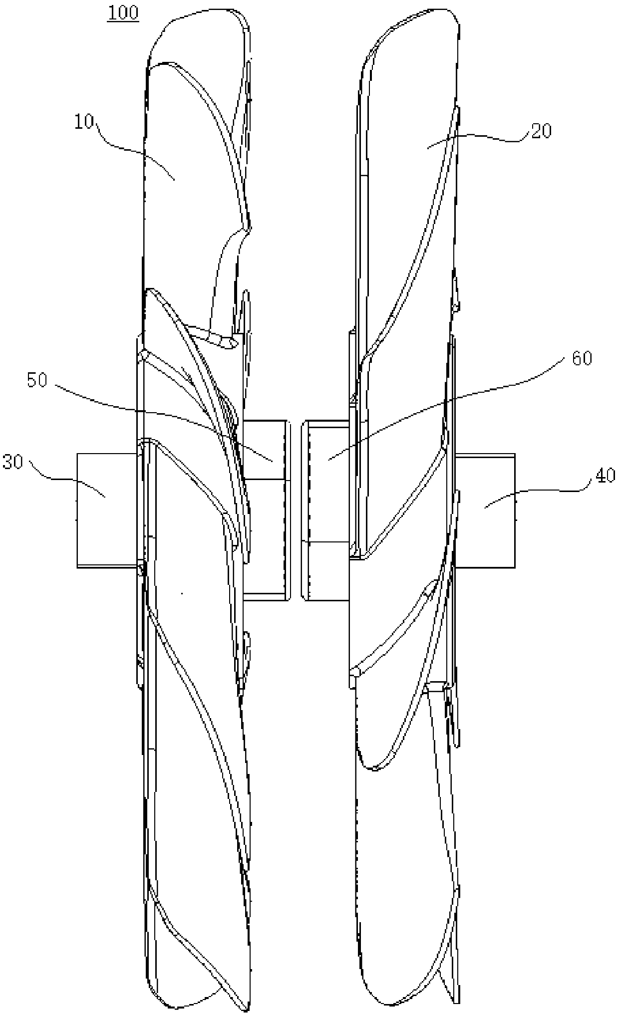
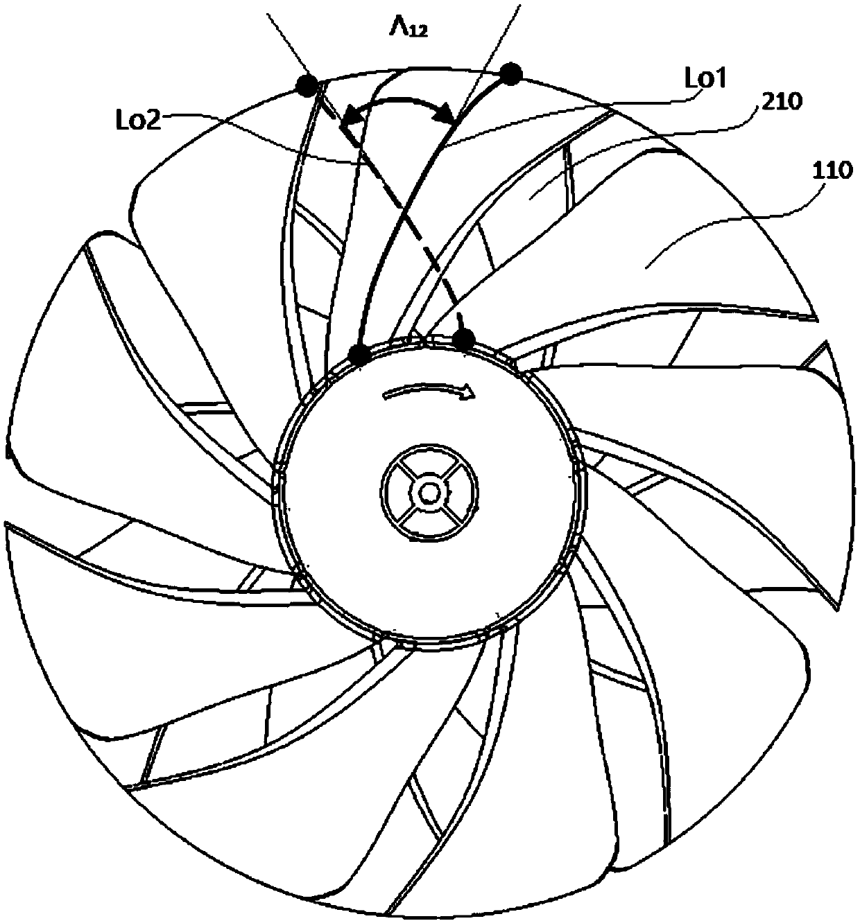
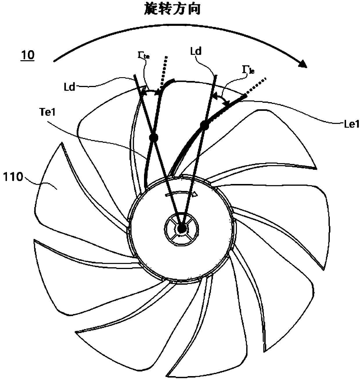
[0055] The counter-rotating fan 100 of this embodiment includes a first stage impeller 10 , a second stage impeller 20 , a first locking nut 30 , a second locking nut 40 , a first driving motor 50 and a second driving motor 60 . The first-stage impeller 10 and the second-stage impeller 20 are coaxial and spaced apart. The first locking nut 30 locks the first-stage impeller 10 on the first drive motor 50, and the second locking nut 40 locks the second-stage The impeller 20 is locked on the second driving motor 60 . The rotation directions of the first-stage impeller 10 and the second-stage impeller 20 are opposite. The first-stage impeller 10 includes a plurality of first blades 110 arranged in the circumferential direction. A leading edge Le1 and a first trailing edge Te1, both of the first leading edge Le1 and the first trailing edge Te1 are curved toward the direction of rotation in a radial direction from inside to outside, and the curved protrusion of the first leading edg...


PUM


Abstract

The invention discloses a counter-rotating fan. The counter-rotating fan comprises a first-stage impeller and a second-stage impeller which are coaxial and arranged in a spaced mode, the rotating directions of the first-stage impeller and the second-stage impeller are opposite, the first-stage impeller comprises a plurality of first blades distributed in the circumferential direction, the two sideedges, in the circumferential direction, of each first blade are a first front edge and a first rear edge correspondingly, the first front edges and the first rear edges are bent towards the rotatingdirection in the radial direction from inside to outside, the second-stage impeller comprises a plurality of second blades distributed in the circumferential direction, the two side edges, in the circumferential direction, of each second blade are a second front edge and a second rear edge correspondingly, and the second front edges and the second rear edges are bent towards the rotating direction in the radial direction from inside to outside. According to the counter-rotating fan, the efficiency of the counter-rotating fan is improved, and the rotating noise of the second blades is reducedwhile the pneumatic performance of the second blades is ensured.

Description

technical field [0001] The invention relates to the field of fan equipment, in particular to a counter-rotating fan. Background technique [0002] The counter-rotating blade technology was developed to overcome the high static pressure and provide the pressure equivalent to that of a two-stage fan. Since the counter-rotating fan has no guide vanes in its structure, it also has the characteristics of a relatively compact structure. At first, it was widely used in axial flow fans in the mining industry, etc., and then gradually expanded to military fields such as helicopters, and civilian fields such as cooling fans. [0003] Counter-rotating fans in the related art generally have the following disadvantages: [0004] 1) In the related art, because the angle between the front and rear blades of the counter-rotating fan is 0, although the front and rear blades rotate in different directions, they still overlap periodically, and the trailing edge of the blades of the previous b...

Claims


Application Information

Patent Timeline
Patent Type & Authority Applications(China)
IPC IPC(8): F04D25/08F04D25/16F04D29/32F04D29/38F04D29/66
CPCF04D25/08F04D25/166F04D29/325F04D29/384F04D29/388F04D29/666
Inventor 胡斯特戴龙珍胡小文张辉易榕
Owner GUANGDONG MIDEA WHITE HOME APPLIANCE TECH INNOVATION CENT CO LTD
Why Eureka
Try Eureka