Dry etching device and air pore device fixing on the same

A dry etching and etching technology, which is applied in the direction of electrical components, discharge tubes, plasma, etc., can solve the problems of gas inlet tip discharge, particle pollution, etc., and achieve the effect of reducing particle pollution and other problems

Inactive Publication Date: 2006-02-15
AU OPTRONICS CORP
View PDF0 Cites 0 Cited by
  • Summary
  • Abstract
  • Description
  • Claims
  • Application Information

AI Technical Summary

Problems solved by technology

This will cause problems such as gas inlet tip discharge and particle contamination in the vacuum chamber

Method used


Image

  • Dry etching device and air pore device fixing on the same
  • Dry etching device and air pore device fixing on the same

Examples


Embodiment Construction

[0023] The dry etching device of the present invention can avoid plasma etching near the gas inlet, so that problems such as tip discharge and particle pollution can be effectively reduced. The following will clearly illustrate the spirit of the present invention with diagrams and detailed descriptions. After those skilled in the art understand the preferred embodiments of the present invention, they can be changed and modified by the techniques taught in the present invention without departing from the spirit of the present invention. Spirit and scope.

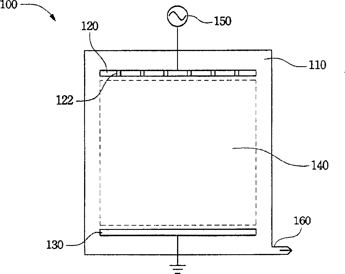
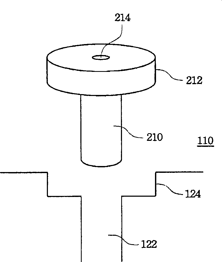
[0024] refer to figure 1 , which is a schematic diagram of a dry etching device according to a preferred embodiment of the present invention. As shown in the figure, the dry etching device 100 is composed of a vacuum chamber 110 , an upper electrode plate 120 , a lower electrode plate 130 , a plasma vacuum discharge area 140 , a power source 150 and a gas outlet 160 . Wherein, the upper electrode plate 120 is installed in t...


PUM


Abstract

The dry etching device with plasma comprises a vacuum cavity with an upper and a lower electrode plate, a vacuum discharging zone for plasma between the two plates, a power source electric connected to the said plates to provide the require potential difference; and a gas output to connect with vacuum cavity and system and maintain plasma state, and it has a resin layer to avoid the etching effect; wherein, there is at least one gas inlet on upper plate to transmit gas.

Description

technical field [0001] The invention relates to a dry etching device, in particular to an air hole device installed in the dry etching device. Background technique [0002] The so-called dry etching (Dry Etching) is a technology of thin film etching with plasma (Plasma). Since the dry etching mainly utilizes the physical phenomenon of particle bombardment for etching, the etching rate of the dry etching in the vertical direction is much higher than that in the lateral direction. Therefore, anisotropic etching is often performed by means of a dry etching process in a thin film process. [0003] A general dry etching device is mainly composed of a vacuum chamber, an upper electrode plate, a lower electrode plate, a plasma vacuum discharge area, a power supply and a gas outlet. Wherein, the upper electrode plate is installed in the vacuum chamber, and has a gas inlet on it, and the gas inlet is used for introducing process gas. Traditionally, the upper electrode plate is mad...

Claims


Application Information

Patent Timeline
Patent Type & Authority Applications(China)
IPC IPC(8): H05H1/46H01L21/00H01L21/3065H01L21/311H01L21/3213H01J37/32
Inventor 江泓庆张奕锟洪国展侯建州
Owner AU OPTRONICS CORP
Why Eureka
Try Eureka