Power cord spooling machine

A technology of power cords and wire winders, which is applied in the direction of circuits, electrical components, and devices with bendable leads, and can solve problems that affect the fastness and reliability of the joint between the plug and the socket, affect the reliability of the electrical contacts, and are messy.

Inactive Publication Date: 2006-02-22
庞一鸣
View PDF1 Cites 21 Cited by
  • Summary
  • Abstract
  • Description
  • Claims
  • Application Information

AI Technical Summary

Problems solved by technology

[0002] At present, the power cords of household appliances are wrapped and hung on the back of the household appliances. After the user unwinds the wires for the first time, he drags the remaining wires behind the machine. With the increase of types of household appliances, the wires are spread out in disorder Hanging, it looks messy, which not only affects the appearance of the interior, but also adds trouble to the relocation
CN2708919Y proposes a wire winder that elastically restores the original shape through the crimping spring, so that the pulled out part can be rolled back into the box, and the length of the power cord can be controlled by this rewinding force, so as to change the dragging phenomenon of the power co

Method used


Image

  • Power cord spooling machine
  • Power cord spooling machine

Examples


Example Embodiment

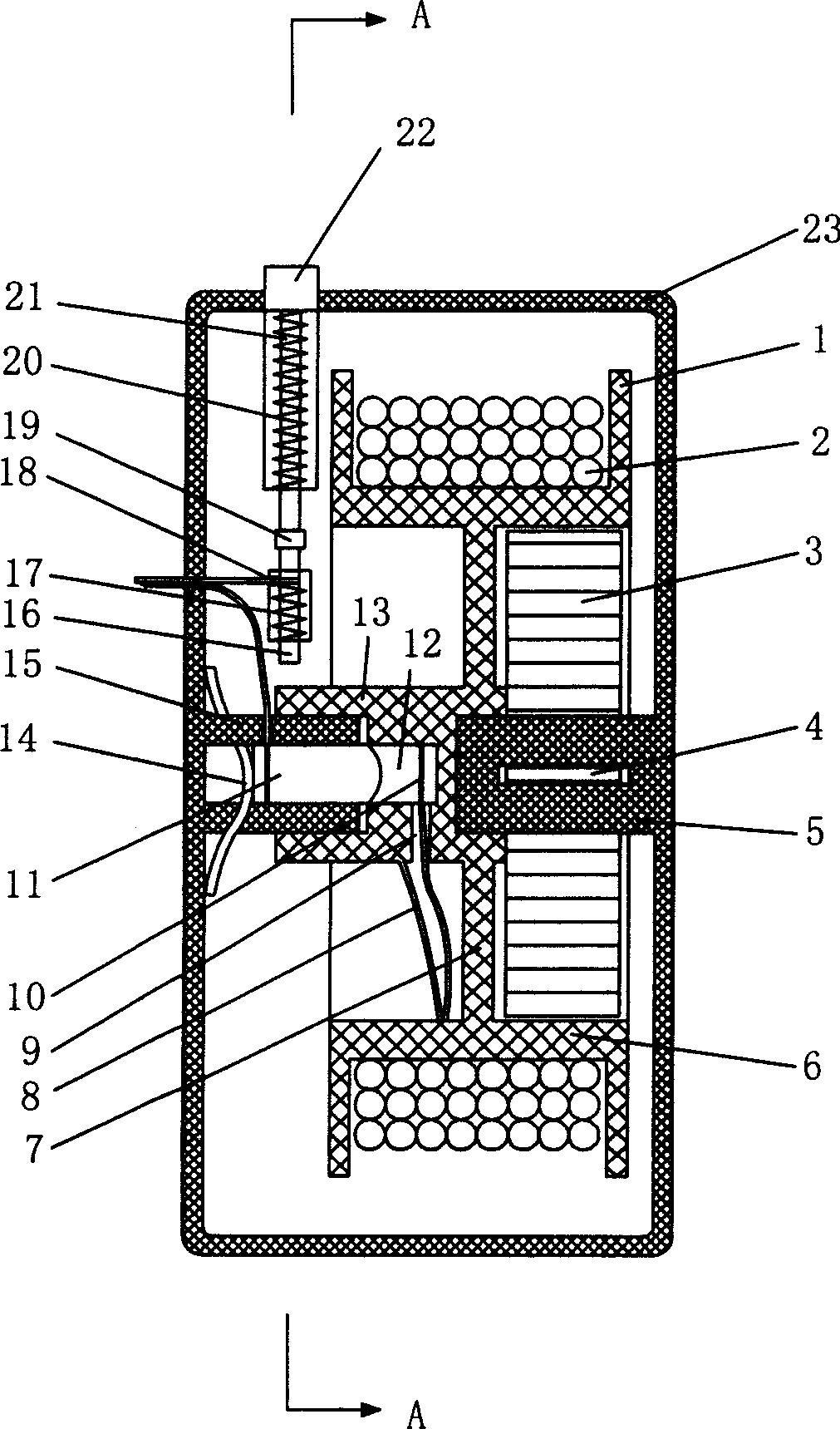
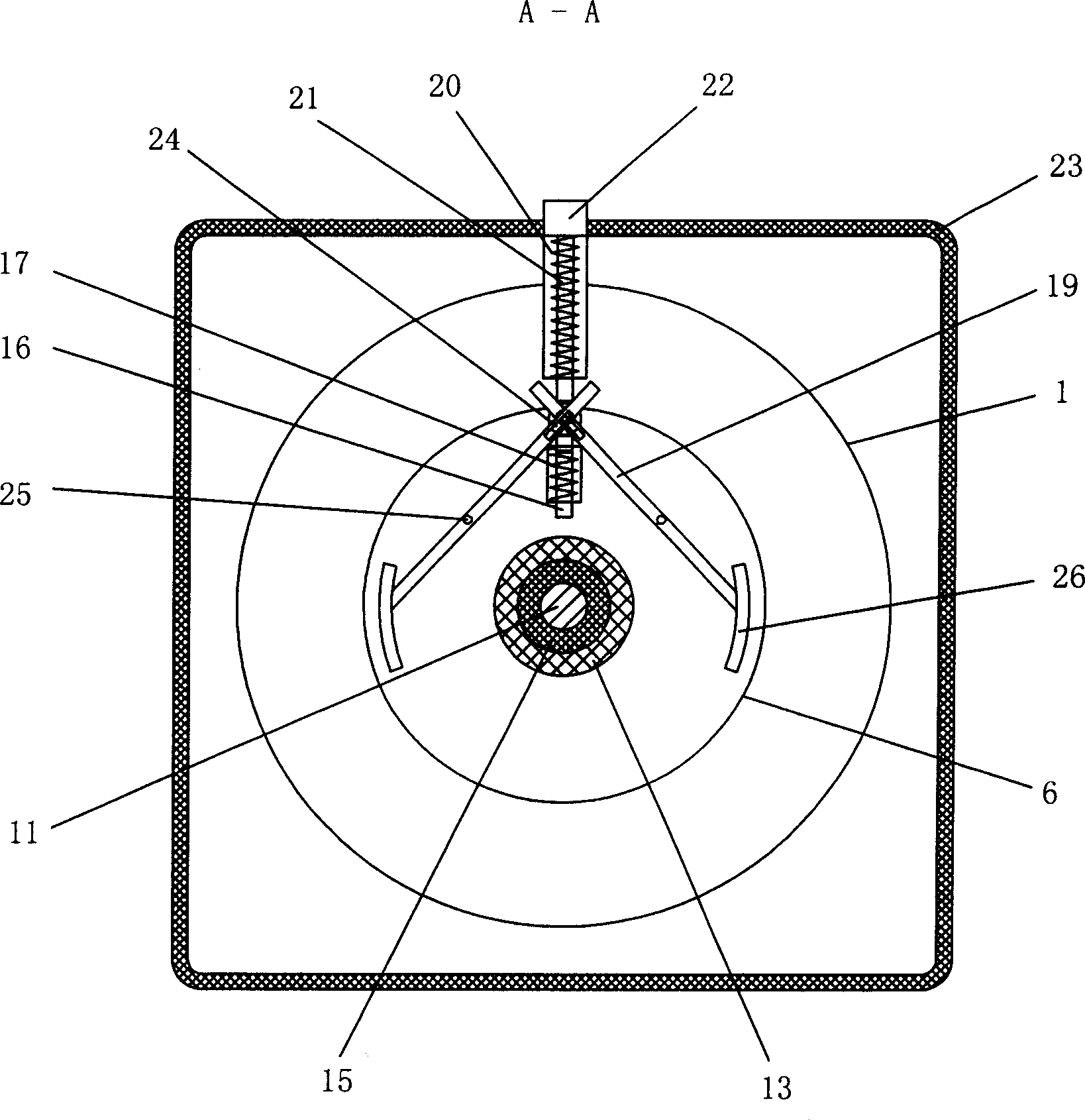
[0010] The utility model is further described below in conjunction with the drawings.

[0011] Reference figure 1 As shown, the winding box 23 includes a crimping spring assembly, a winding power cord assembly, an electrical connection assembly, and a stop joint assembly. The coil spring assembly includes a coil spring sheet 3, which is wound around the coil spring shaft core 5 in a concentric manner with the coil spring shaft core 5 as the center. One end of the coil spring shaft core 5 is fixed to the winding box 23, The crimping spring piece 3 is fixed by the crimping elastic piece socket 4 on one end of the crimping spring shaft core 5, and the other end is fixed at the base of the winding wheel 6. When the power cord 2 wound on the reel 6 is pulled, the reel 6 rotates to drive one end of the crimping spring fixed at the base of the reel 6 to rotate, so that the crimping spring sheet takes its fixed shaft core as The center rotates and gradually tightens to generate a crimpin...


PUM


Abstract

Disclosed a coiling machine for power cord comprises a coiling box, a coiling wheel inside the coiling box, limited rings on the two ends of coiling wheel, and crinkle spring inside the coiling axle sleeve to connect the coiling axle corn. The invention is characterized in that the protruded part of coiling axle sleeve is equipped a electric connecting component formed by a conducting outer layer, a insulated inner layer and a conducting axle corn; a coiling-proof wheel formed by stop arm and vertical binding post is arranged on the outside of limited ring, as a stop connecting component which can rotate to make a group of electrical contacts connect. The stop function which is synchronous to the electrical connection can reduce the tensity between plug and the power cord, to make the plug connect the adapter firmly; in addition, it coils without electric to improve the safety of household appliance which also can prevent the knotting inside the box.

Description

Technical field [0001] The invention relates to a wire winding appliance, in particular to a wire take-up box for power cords of household appliances. Background technique [0002] At present, the power cords of household appliances are wound behind the household appliances by the power cord itself. After the user loosens the winding for the first time, the remaining cord is dragged behind the machine. As the types of household appliances increase, the wires are spread out in all directions. Hanging, it looks messy, not only affects the interior appearance, but also adds trouble to the relocation. CN2708919Y proposes a wire winder to restore its original shape through a crimping spring, so that the pulled part can be rolled back into the box. This rewinding force is used to control the length of the power cord and change the dragging phenomenon of the power cord. The resilience of the spring is proportional to the length that is pulled out. The longer the length is, the greater t...

Claims


Application Information

Patent Timeline
IPC IPC(8): H01R13/72H01R13/70B65H75/34
Inventor 庞一鸣
Owner 庞一鸣
Why Eureka
Try Eureka