Engine pendant

A suspension device and engine technology, applied in transportation and packaging, special foundation layout, supporting machines, etc., can solve problems such as poor stability, damage, and fracture of the swing engine 2

Inactive Publication Date: 2006-03-01
KYMCO
View PDF0 Cites 4 Cited by
  • Summary
  • Abstract
  • Description
  • Claims
  • Application Information

AI Technical Summary

Problems solved by technology

[0004] Mainly due to the flexibility of the rubber bushing 124, it can passively absorb the torsion generated by the swing engine 2 during torsion and vibration, so as to prevent the structure of the motorcycle engine hanger device 1 from being unable to withstand excessive torsional vibration of the swing engine 2 The torsion and vibration force transmitted, resulting in breakage and damage
However, on the contrary, the flexible rubber bushing 124 obviously cannot actively suppr

Method used


Image

  • Engine pendant
  • Engine pendant
  • Engine pendant

Examples


Embodiment Construction

[0017] The aforementioned and other technical contents, features and effects of the present invention will be clearly understood in the following detailed description of a preferred embodiment with reference to the drawings.

[0018] refer to Figure 4 and Figure 5 , is the preferred embodiment of the engine suspension device 6 of the present invention, which is used to suspend and assemble a swing engine 4 of a motorcycle on the vehicle frame 5 of the motorcycle. The swing engine 4 has two lug bearings 41 spaced apart.

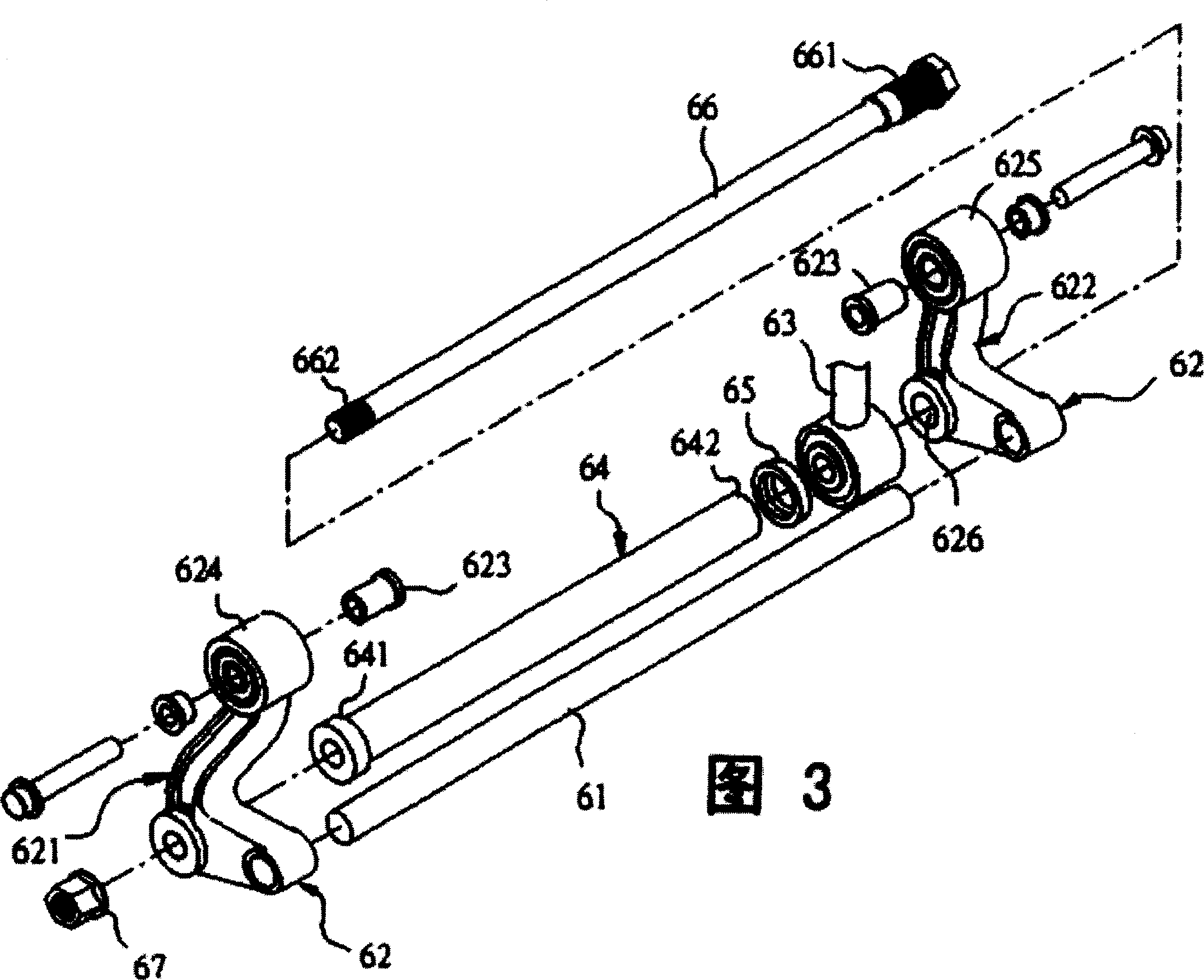
[0019] See Figure 3 with Figure 4 The engine suspension device 6 includes a connecting rod 61 located above the two lug bearings 41 and having a length greater than the distance between the two lug bearings 41, a frame locking unit 62, a tie rod seat 63, and a The positioning sleeve 64 in the two lug bearings 41 , a positioning sleeve cover 65 , a fixed shaft 66 , and a lock attachment 67 .

[0020] The frame locking unit 62 has a first locking seat 621 ,...


PUM


Abstract

The engine pendant for assembling swinging engine with two lifting eye bearings onto frame includes one first locking seat, one second locking seat, one locating sleeve penetrating the lifting eye bearings, one locating sleeve cover, and one fixing rod locked to the second locking seat. The locating sleeve has one limiting end fastening one of the lifting eye bearings and the other externally stretched end. The fixing rod is locked to the second locking seat to make the limiting end of the locating sleeve and the locating sleeve cover to fasten these two lifting eye bearings separately. The present invention has excellent overall support rigidity, raised transverse rigidity of the swinging engine to the frame, and effectively raised execution stability of the swinging engine.

Description

【Technical field】 [0001] The invention relates to an engine suspension device, in particular to an engine suspension device which has good support rigidity and can effectively improve engine stability. 【Background technique】 [0002] Referring to FIG. 1 and FIG. 2 , it is a conventional motorcycle engine hanger device 1 for suspending and assembling a swing engine 2 for a motorcycle on the frame 3 of the motorcycle. The motorcycle engine hanger device 1 includes a main frame bar 11 and two fixing units 12 respectively fixed at two ends of the main frame bar 11 . The two fixing units 12 respectively have a first frame lock seat 121, a second frame lock seat 122, an engine lock seat 123, and a press-fitted seat 121 which is arranged in the first frame lock seat 121. A rubber bushing 124 and a rubber stopper 125 are press-fitted in the second frame lock seat 122 . The first and second vehicle frame lock seats 121, 122 are locked together with the vehicle frame 3, and the engi...

Claims


Application Information

Patent Timeline
IPC IPC(8): B62M7/06F16M9/00
Inventor 喻润湘
Owner KYMCO
Why Eureka
Try Eureka