Riving knife assembly for table saws

A technology of components and riving knives, which is applied in the direction of sawing components, circular saws, sawing machine devices, etc., and can solve the problem of difficult disassembly of riving knife components

Inactive Publication Date: 2006-03-08
BLACK & DECKER INC
View PDF0 Cites 3 Cited by
  • Summary
  • Abstract
  • Description
  • Claims
  • Application Information

AI Technical Summary

Problems solved by technology

The riving knife assembly is generally difficult to remove from the table saw

Method used


Image

  • Riving knife assembly for table saws
  • Riving knife assembly for table saws
  • Riving knife assembly for table saws

Examples


Embodiment Construction

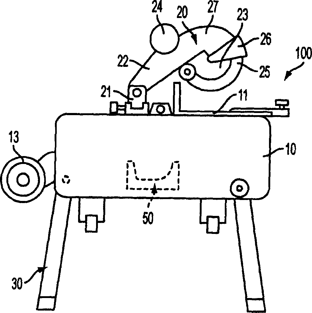
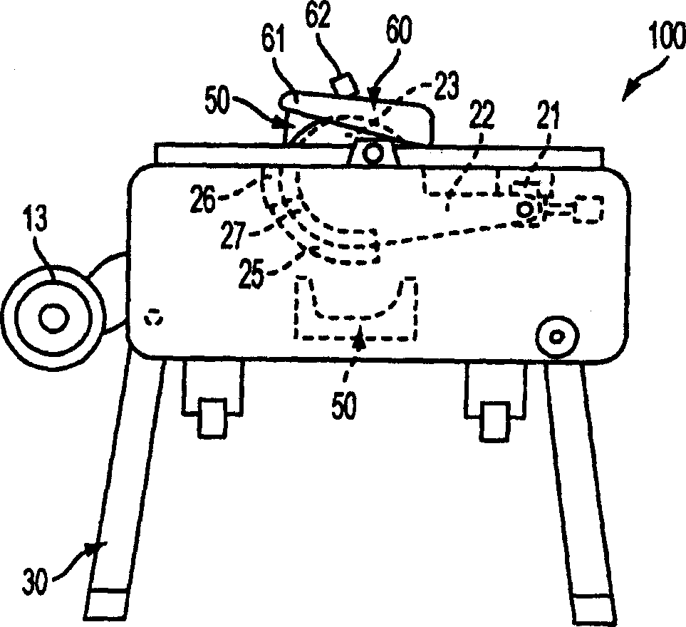
[0012] The invention will now be described with reference to the drawings, wherein like reference numerals refer to like parts. Referring to FIG. 1 , a table / miter saw combination saw 100 may include a base assembly 10 , a table 11 supported by the base assembly 10 , and a saw assembly 20 supported by the table 11 . The saw assembly 20 may include a trunnion 21 disposed on the table 11 , a pivot arm 22 pivotally connected to the trunnion 21 , a motor 24 supported by the arm 22 and driving a saw blade 23 . The arm 22 also supports an upper blade guard 27 which covers the upper portion of the blade 23 . The lower blade guard 25 is pivotally connected to the upper blade guard 27 . An auxiliary blade guard 26 is pivotally connected to the lower blade guard 25 .

[0013] Workbench 11 is preferably pivotally connected to base assembly 10 via connection 15 so that when workbench 11 is in Figure 1A When in the direction of the table 11, the saw assembly 20 can be used as a miter s...


PUM


Abstract

A power tool having a base assembly, a table supported by the base assembly, a saw assembly supported by the table, and a riving knife assembly attached to the saw assembly. The riving knife has a body with an edge placed adjacent to a blade, and a bracket connected to the body. The bracket is inserted into a support assembly disposed on the saw assembly.

Description

technical field [0001] The present invention relates generally to a riving knife assembly for a table saw, and more particularly to a riving knife assembly for a table saw / miter saw combination saw. Background technique [0002] In the field of table saws, it is well known that a table saw blade is provided with a riving knife assembly behind the blade. Ripping knife assemblies are generally difficult to remove from table saws. It is therefore an object of the present invention to provide an improved riving knife assembly. Contents of the invention [0003] According to the invention, an improved support assembly is used. A power tool has a base assembly, a table supported by the base assembly, a saw assembly supported by the table, and a riving knife assembly connected to the saw assembly, the riving knife including a body having an edge disposed adjacent a saw blade and a A bracket connected to the upper part, wherein the bracket is inserted into the support assembly ...

Claims


Application Information

Patent Timeline
Patent Type & Authority Applications(China)
IPC IPC(8): B23D47/02B23D45/14B23Q11/08
CPCB27B5/165Y10T83/773B27G19/08Y10T83/856
Inventor 罗伯特·S·格雷特罗伯特·库斯米尔斯基小马克·D·米勒
Owner BLACK & DECKER INC
Why Eureka
Try Eureka