
Cast-in-situ concrete filled hollow stuffing

A hollow carcass, cast-in-place concrete technology, which is applied to the on-site preparation of building components, formwork/template/work frame, structural elements, etc., can solve problems such as affecting construction efficiency and inconvenient transportation and construction.

Inactive Publication Date: 2006-03-08
湖南邱则有专利战略策划有限公司
View PDF2 Cites 1 Cited by
  • Summary
  • Abstract
  • Description
  • Claims
  • Application Information

AI Technical Summary

Problems solved by technology

These formwork components are inconvenient during transportation and construction, which affects construction efficiency. Therefore, it is urgently needed to develop a new type of hollow matrix for filling in-situ concrete.

Method used


Image

  • Cast-in-situ concrete filled hollow stuffing
  • Cast-in-situ concrete filled hollow stuffing
  • Cast-in-situ concrete filled hollow stuffing

Examples


Embodiment Construction

[0068] The present invention will be further described below in conjunction with the accompanying drawings and embodiments.

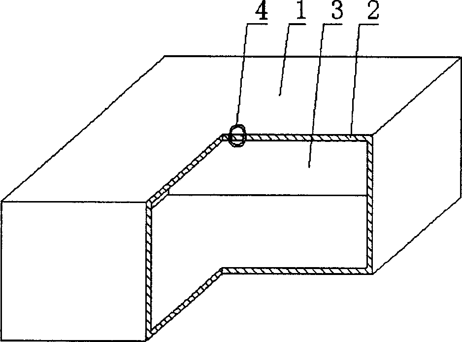
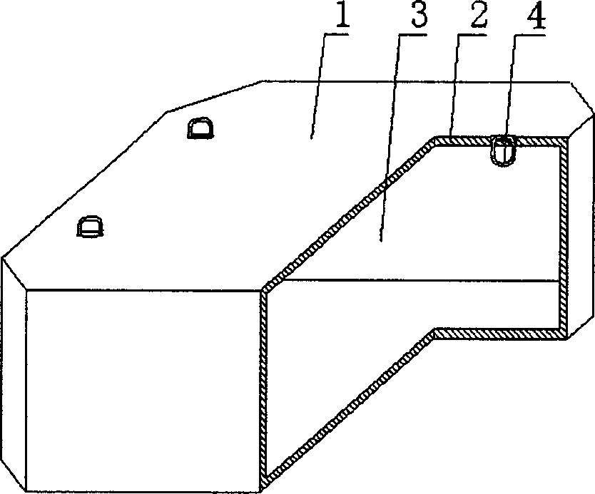
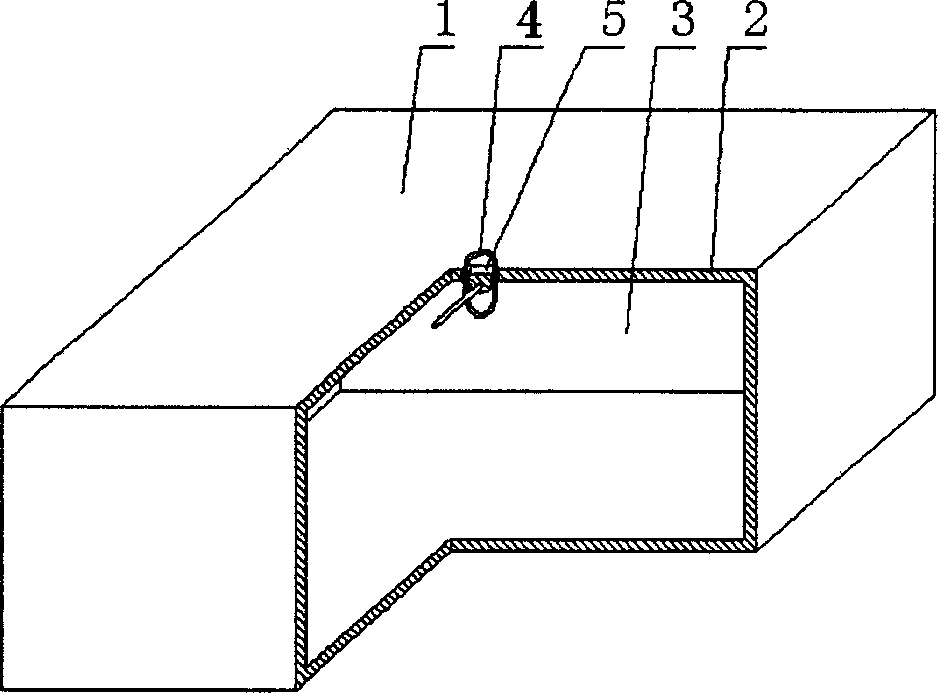
[0069] As shown in the accompanying drawings, the present invention includes a hollow carcass 1, and the outer wall 2 encloses the hollow carcass 1 with a cavity 3, and is characterized in that the outer wall 3 on the hollow carcass 1 has the ability to pass through the outer wall 3 The lifting ring 4. In each accompanying drawing, 1 is a hollow carcass, 2 is an outer wall, 3 is a cavity, and 4 is a suspension ring. In the following accompanying drawings, those with the same number have the same description. Such as figure 1 As shown, the outer wall 2 encloses a hollow carcass 1 formed with a cavity 3 , and the top outer wall 2 on the hollow carcass 1 is provided with a movable suspension ring 4 passing through the top outer wall 2 .

[0070] The present invention is also characterized in that the suspension ring 4 is lower than or flush with the surf...


PUM


Abstract

A hollow roughcast for the filling of cast-in-place includes a hollow roughcast, an outside wall to be closed to form a hollow roughcast with a cavity characterizing that a movable hanging ring passing through the outside wall is set on the wall, so it's very easy for the hollow roughcast to be transported in construction and the hanging ring will not be broken or harm the hollows roughcast on it when the roughcast are hoisted or stacked.

Description

(1) Technical field [0001] The invention relates to a hollow matrix for filling cast-in-place concrete. (2) Background technology [0002] At present, the cast-in-place concrete floor is a widely used floor structure. The lightweight permanent tire mold filled in it has various hollow tubes and boxes, and the boxes are hollow or solid. For example, the patent No. ZL00203695.9 applied by Liang Jun, Shijiazhuang City, Hebei Province on February 23, 2000, is called the utility model patent of "combined concrete concealed rib floor cover", and a formwork member is disclosed in its specification sheet. It can be solid or hollow, and its shape can be made into rectangle, circle, polygon and other shapes according to design requirements. Another example is the utility model patent No. ZL99249798.1, which the applicant applied for on November 29, 1999, entitled "fiber-reinforced thin-walled components for reinforced concrete filling", which discloses a thin-walled formwork componen...

Claims


Application Information

Patent Timeline
IPC IPC(8): E04G15/06E04B5/36E04C5/00E04C5/16E04B5/48
Inventor 邱则有
Owner 湖南邱则有专利战略策划有限公司
Features
  • Generate Ideas
  • Intellectual Property
  • Life Sciences
  • Materials
  • Tech Scout
  • Unparalleled Data Quality
  • Higher Quality Content
  • 60% Fewer Hallucinations
Learn More