

Automatic detection method of jitter of video
A technology for video jitter and automatic detection, applied in the field of digital video, can solve the problem of lack of detection methods and standards in digital video, achieve high accuracy, improve efficiency and effect.
- Summary
- Abstract
- Description
- Claims
- Application Information
AI Technical Summary
Problems solved by technology
Method used
Image

Examples
Embodiment Construction
[0022] The present invention will be described in detail below in conjunction with specific embodiments. The following examples will help those skilled in the art to further understand the present invention, but do not limit the present invention in any form. It should be noted that those skilled in the art can make several modifications and improvements without departing from the concept of the present invention. These all belong to the protection scope of the present invention.
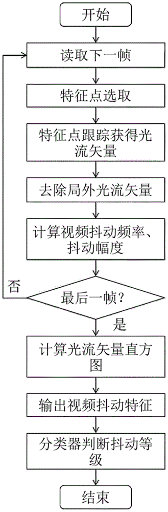
[0023] Such as figure 1 As shown, it is an overall flowchart of an embodiment of the present invention, specifically including:
[0024] The first step is to select the feature points in the current video frame;
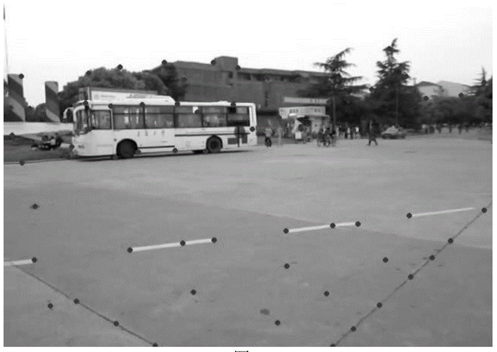
[0025] The second step is to track the matching feature points in adjacent frames to obtain the inter-frame optical flow vector;
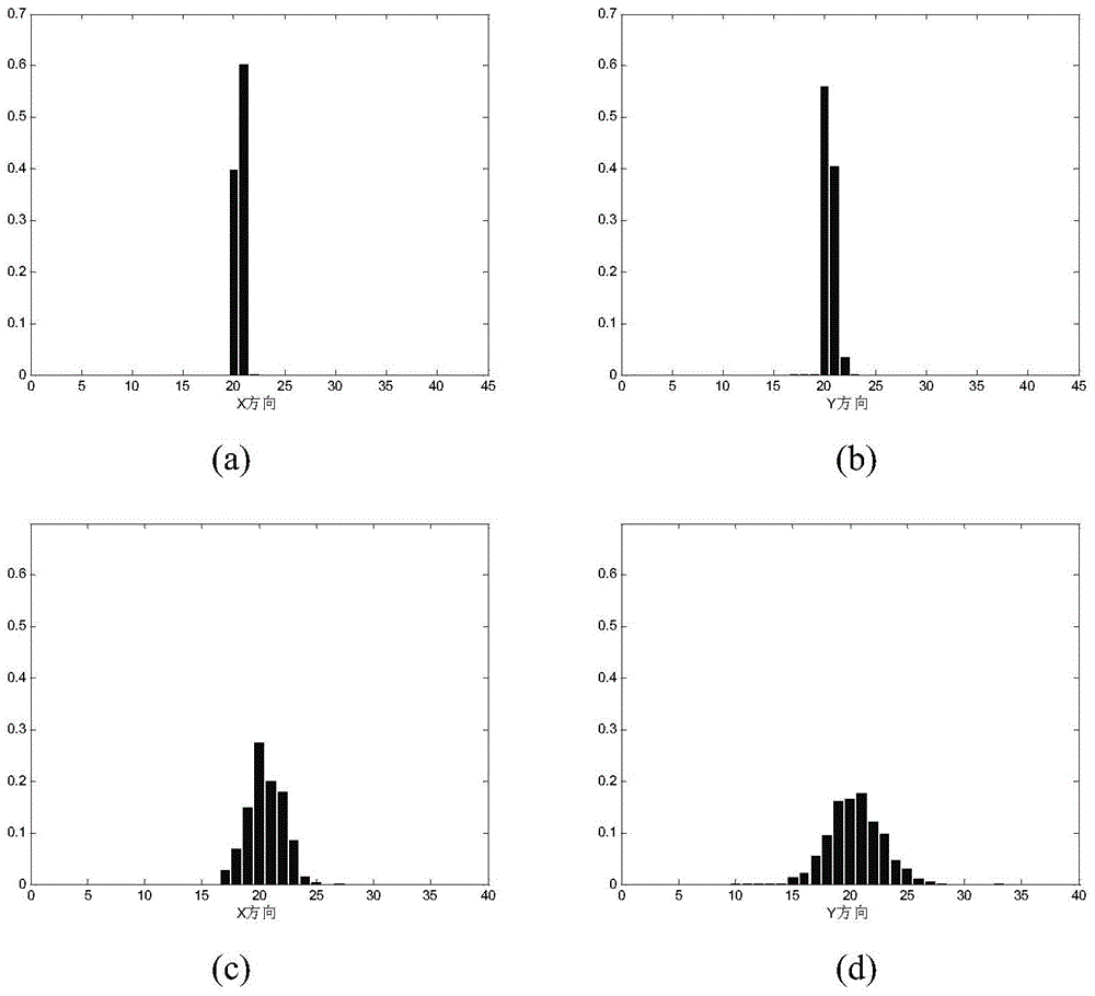
[0026] The third step is to remove outliers from the inter-frame optical flow vectors obtained in the second step; in the removal of abnormal optical flow...
PUM
 Abstract
Description
Claims
Application Information