Cursor for electronic devices

A technology for electronic equipment and cursors, which is applied in electrical digital data processing, structural components of portable computers, input/output processes of data processing, etc., and can solve the problems of small size, insufficient space for separation, and inability to be effectively used, etc. To achieve the effect of fast movement

Inactive Publication Date: 2006-03-15
MOTIONIP
View PDF0 Cites 8 Cited by
  • Summary
  • Abstract
  • Description
  • Claims
  • Application Information

AI Technical Summary

Problems solved by technology

The problem with this solution is that, for example, when using electronic equipment, not enough space is separated for the above-mentioned obvious areas
Even when a distinct area is provided to show the user's current location within the overall digital profile, its size is too small to be used effectively

Method used


Image

  • Cursor for electronic devices
  • Cursor for electronic devices
  • Cursor for electronic devices

Examples


Embodiment Construction

[0024] Reference will now be made in detail to embodiments of the invention, examples of which are illustrated in the accompanying drawings.

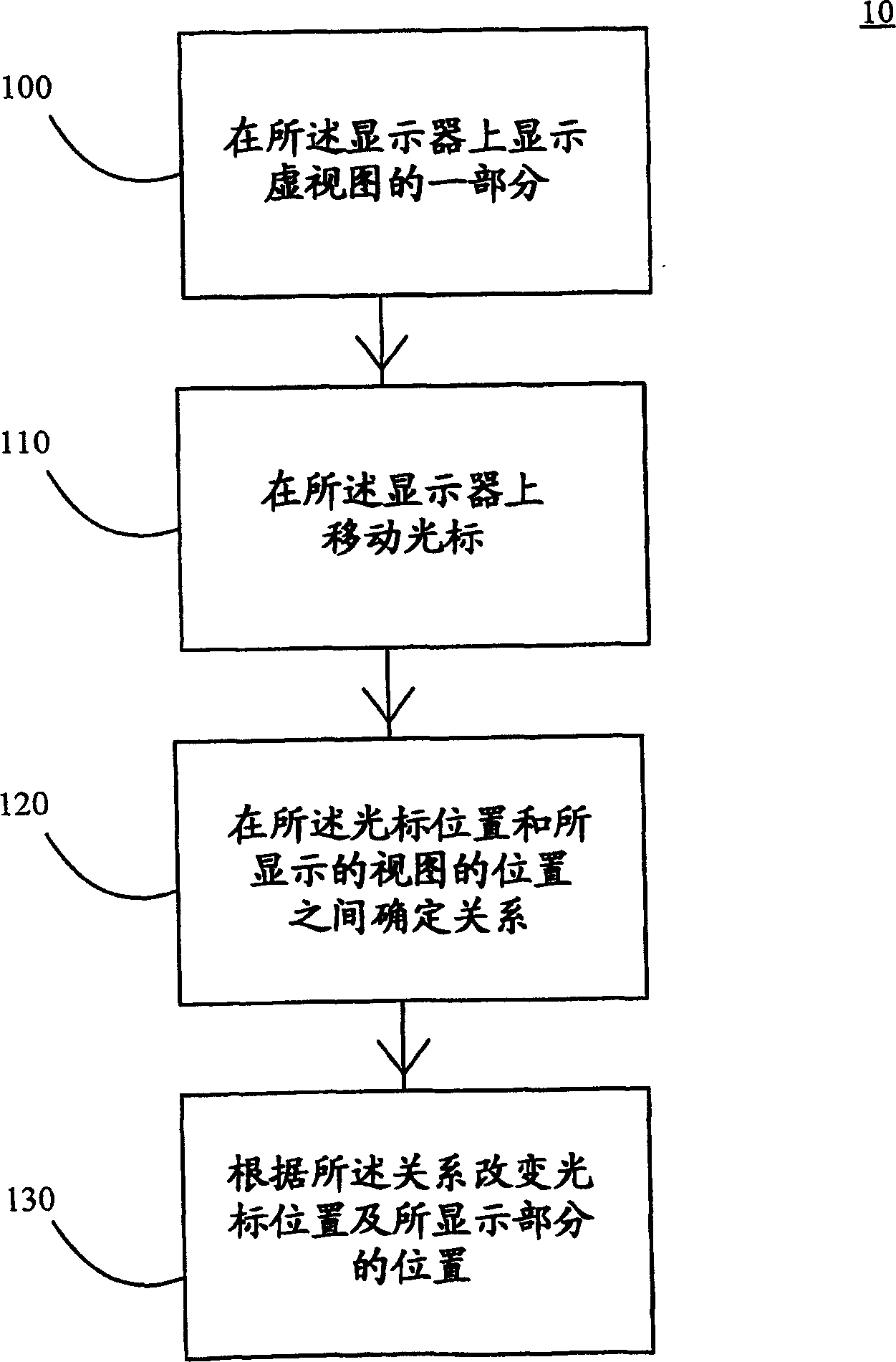
[0025] refer to figure 1 And stage 100, a part of the whole virtual view is displayed on the display. The displayed portion may be in any scale or ratio to the overall virtual view. At stage 110, a cursor is moved on the display. The cursor may be moved by a mouse, selection of keys, touch pad, joystick or any other device suitable for moving a cursor. In stage 120, a relationship between the position of the cursor and the position of the displayed view is determined.

[0026] In some embodiments, the relationship is linear, while in other embodiments it is progressive with departure from the origin and so on. In some embodiments, the cursor, virtual view and / or displayed portion have the same origin. In step 130, the position of the cursor and the position of the displayed part are changed according to the relationship.

[0027] ...


PUM


Abstract

The present invention describes a method, electronic device and computer program for displaying a cursor on the display of an electronic device. The size of the display is typically so small that only part of a virtual view is displayed at one time on the display. The user of the electronic device changes the displayed part of the virtual view on the display. In the present invention, a correlation between the cursor location on the display and the location of the displayed part of the virtual view within the whole virtual view is determined so that the cursor location on the display reflects the location of the displayed part of the virtual view in proportion to the whole virtual view. In other words, the user can quickly perceive the exact location e.g. on the virtual desktop or in large digital material displayed on the display of an electronic device.

Description

technical field [0001] The present invention relates to electronic equipment. In particular, the present invention relates to a novel and improved method for computer programs and electronic devices to know their current location in a virtual view larger than the physical display. Background technique [0002] The display size of an electronic device places certain constraints on the presentation of information on the display. Small displays are not the best place to present large amounts of information. If the amount of information is large and all information is presented on the display at the same time, details may become blurred. One solution to this problem is the so-called "virtual desktop". Therein, the entire amount of digital information is represented at the same time in a larger space than the actual amount of information presented on the display of the device. Therefore, means are needed for accessing information represented outside of the viewable area. Thi...

Claims


Application Information

Patent Timeline
Patent Type & Authority Applications(China)
IPC IPC(8): G06F3/033G06F1/16G06F3/0485
CPCG06F1/1694G06F1/1613G06F3/0485G06F2200/1637
Inventor J·韦内宁
Owner MOTIONIP
Why Eureka
Try Eureka