

Cuff for blood pressure monitor
A sphygmomanometer and cuff technology, applied in vascular assessment, cardiac catheterization, etc., can solve the problems of decreased hemostatic performance, failure to suppress the wrinkling and bending of the air bag used for blood expelling, and decreased accuracy of blood pressure measurement, and achieve stable hemostatic The effect of the function
- Summary
- Abstract
- Description
- Claims
- Application Information
AI Technical Summary
Problems solved by technology
Method used
Image


Examples
no. 1 approach
[0053] figure 1 It is a schematic cross-sectional view showing the structure of the cuff for a blood pressure monitor according to the first embodiment of the present invention, and is a diagram showing an attached state in which the cuff for a blood pressure monitor is wound around a wrist. Such as figure 1 As shown, the sphygmomanometer cuff 1A of this embodiment mainly includes: an air bag 10A as a fluid bag; The loop 20 of the component; the strap 30 for fixing the cuff 1A on the body. The outer peripheral surface of the air bag 10A is fixed to the inner peripheral surface of the collar 20 . In addition, the outer peripheral surface of the collar 20 is fixed to the inner peripheral surface of the binding band 30 .
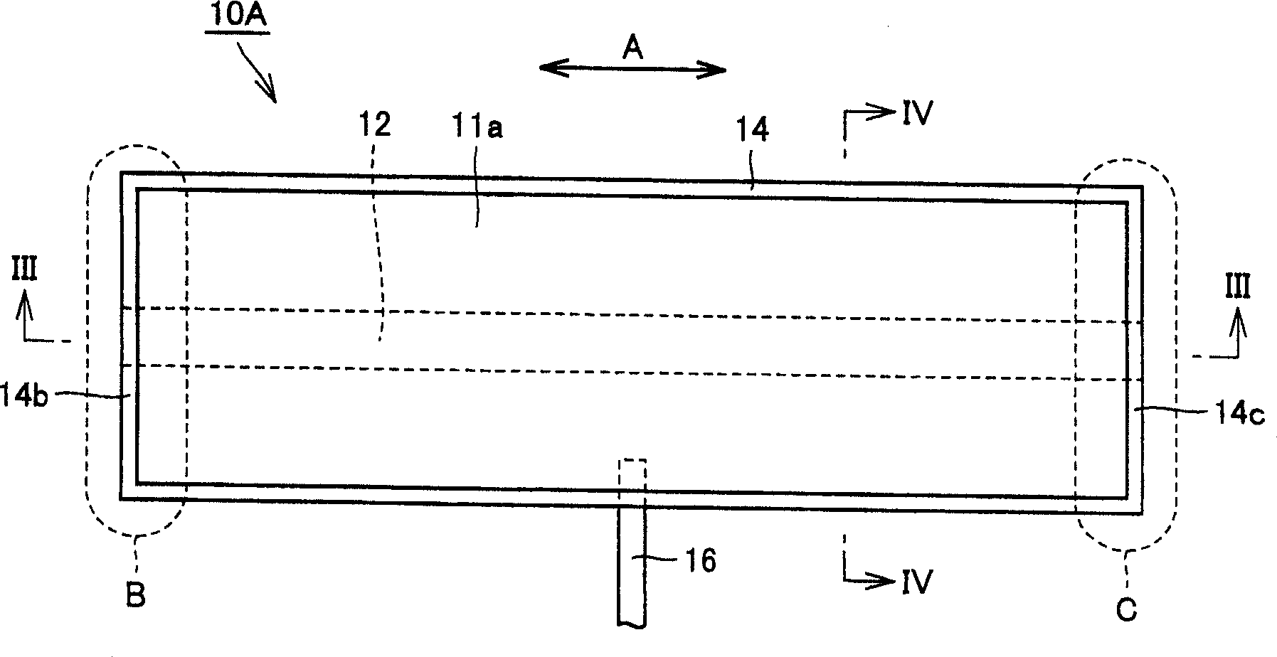
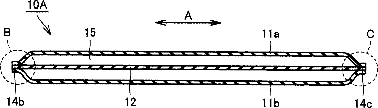
[0054] figure 2 is to make figure 1 A schematic plan view of the state in which the air bag is deployed is shown. image 3 is to mean along figure 2 The schematic cross-sectional view of line III-III in the figure of the air bag shown, Figure 4 is...
no. 2 approach
[0067] Figure 7 is a schematic cross-sectional view of the air bag along the winding direction of the cuff for blood pressure monitor according to the second embodiment of the present invention, Figure 8 It is a schematic cross-sectional view of the air bag along a direction perpendicular to the winding direction of the blood pressure cuff according to this embodiment. In addition, the cuff for a blood pressure monitor of this embodiment is the same as the cuff for a blood pressure monitor of the above-mentioned first embodiment except for the configuration of the air bag. Therefore, only the differences in the structure of the air bag will be described below, and the same parts in the air bag will be given the same reference numerals in the drawings, and the description will not be repeated here.
[0068] Such as Figure 7 and Figure 8 As shown, in the air bladder 10B of the cuff for blood pressure monitor of this embodiment, like the air bladder 10A of the cuff for blo...
no. 3 approach
[0076] Figure 12 It is a schematic plan view showing the structure of the air bag of the blood pressure cuff according to the third embodiment of the present invention. In addition, the cuff for a blood pressure monitor of this embodiment is the same as the cuff for a blood pressure monitor of the above-mentioned first embodiment except for the configuration of the air bag. Therefore, only the differences in the structure of the air bag will be described below, and the same parts in the air bag will be given the same reference numerals in the drawings, and the description will not be repeated here.
[0077] Such as Figure 12 As shown, in the air bag 10E of the blood pressure cuff of the present embodiment, similar to the air bag 10A of the blood pressure cuff 1A of the first embodiment described above, the air bag 10A formed by the outer wall portion 11a and the inner wall portion 11b is inflated. The belt-shaped connecting portion 12 is arranged in the shrinkage space 15 ...
PUM
 Abstract
Description
Claims
Application Information