

Data transmission system, data transmission method, and media apparatus
A technology of data transmission system and media equipment, applied in the direction of transmission system, electrical components, etc., can solve problems such as virtual connection and actual connection connection that are not mentioned
- Summary
- Abstract
- Description
- Claims
- Application Information
AI Technical Summary
Problems solved by technology
Method used
Image

Examples
Embodiment Construction
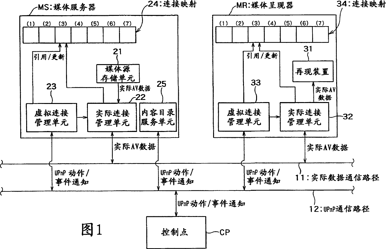
[0029]FIG. 1 is a block diagram showing an example of a transmission system according to the present invention. The media server MS, media renderer MR and control point CP are connected to each other through a network such as a home network. The media server MS, media renderer MR, and control point CP can execute programs according to the UPnP AV protocol. The UPnP AV protocol and specifications related to the UPnP AV protocol are found in e.g. "http: / / www.upnp.org / standardizeddcps / mediaserver.asp" "UPnP AVArchiteture v0.83, June 12, 2002", "Connection Managerv1.0, June 25 , 2002", "Designing a UPnP AV Media Renderer V1.0, Intel Corporation, 2003 (http: / / www.intel.com / technology / upnp / download / Designing_a_UPnP_AV_MediaRenderer_v1_0-XF.pdf)", "Designing a UPnP AV Media Server V1.0, Intel Corporation, 2003 (http: / / www.intel.com / technology / upnp / download / Designing_a_UPnP_AV_Mediaserver_v1_0-XF.pdf)" is described.
[0030] In FIG. 1, the media server MS is, for example, a DVD play...
PUM
 Abstract
Description
Claims
Application Information