Matrix display

A matrix display and pixel matrix technology, applied to static indicators, instruments, etc., can solve the problem of high impedance of photosensitive elements

Inactive Publication Date: 2006-03-22
KONINKLIJKE PHILIPS ELECTRONICS NV
View PDF1 Cites 4 Cited by
  • Summary
  • Abstract
  • Description
  • Claims
  • Application Information

AI Technical Summary

Problems solved by technology

In the unselected rows, the selected light-emitting elements do not produce light, so the impedance of the photosensitive elements of the unselected pixels is high

Method used


Image

  • Matrix display
  • Matrix display
  • Matrix display

Examples


Embodiment Construction

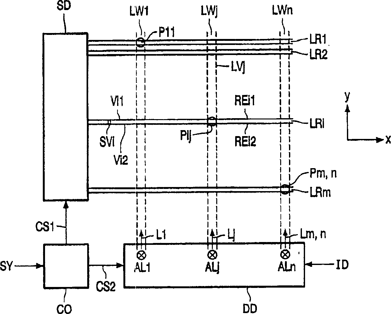
[0032] figure 1 An embodiment of a matrix display device with optically addressed display elements with optical feedback is represented to obtain a memory effect of the pixels.

[0033] The matrix display comprises a matrix of pixels Pij (P11-Pmn) associated with the intersections of light guides LWj (LW1-LWn) and sets of two row electrodes REi1, REi2. The index i represents the number of rows of the matrix display, and the index j represents the number of columns of the matrix display. The row electrodes REi1 and REi2 extend in the x direction, and the optical waveguide LWj extends in the y direction. In a transposed matrix display, the x and y directions are interchanged.

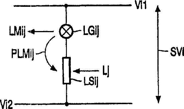
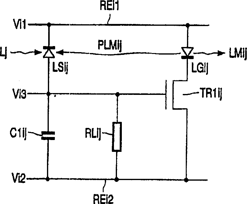
[0034] The selection driver SD applies the row voltage Vil to the row electrode REi1, and applies the row voltage Vi2 to the row electrode REi2. The pixel voltage SVi is generated between the row electrode REi1 and the row electrode REi2 of the i-th row.

[0035]The data driver DD receives the input d...


PUM


Abstract

A matrix display device comprises a matrix of optically addressable pixels (Pij) which comprise a light sensitive element (LSij) and a pixel light generating element (LGij). The light generating element (LGij) will produce a pixel light (LMij) with a brightness which depends on the state of the light sensitive element (LSij). The state of the light sensitive element (LSij) depends on the amount of light impinging on it. The actual brightness of the pixel light generating element (LGij) may further depend on a voltage across it. The pixels (Pij) are constructed such that a portion of the pixel light (PLMij) generated by the pixel light generating element (LGij) reaches the associated light sensitive element (LSij) of the pixel (Pij). The light sensitive element (LSij) is sensitive to the portion of the pixel light (PLMij) to obtain a feedback of the portion of the pixel light (PLMij) to the light sensitive element (LSij). This feedback may be used to obtain a memory behavior of the pixel (Pij) or to influence an intrinsic memory behavior of the pixel (Pij).

Description

technical field [0001] The invention relates to an active matrix display, and a display device comprising the matrix display. Background technique [0002] US-B-6215462 discloses a matrix display device with rows of pixels. The rows of the matrix display are selected one by one. Each row is associated with an optical waveguide that delivers light generated by the first light-emitting element to the pixels of that row. A particular row is selected if the associated selected light emitting element produces light; all other rows are not selected because their associated selected light emitting element is not producing light. [0003] Each pixel includes a series arrangement of a photosensitive element and a pixel light emitting element. Data voltages corresponding to image data to be displayed are delivered to the series arrangement via the column conductors. In the selected row of pixels, the light generated by the selected light-emitting element associated with the select...

Claims


Application Information

Patent Timeline
Patent Type & Authority Applications(China)
IPC IPC(8): G09G3/02G09G3/20G09G3/32
CPCG09G2300/0842G09G3/3208G09G3/20G09G3/3233G09G2300/088G09G3/02G09G3/3216G09G2360/148G09G2360/142
Inventor M·P·C·M·克里恩F·P·M·布德泽拉亚尔J·J·L·霍普彭布劳维斯M·梅亚尼J·J·W·M·罗辛克B·A·萨特斯
Owner KONINKLIJKE PHILIPS ELECTRONICS NV
Why Eureka
Try Eureka