Fume exhaustor for kitchen

A technology for range hoods and kitchens, applied in the direction of oil fume removal, application, and household stoves, etc., which can solve problems such as rising costs, increasing thickness, and increasing noise

Inactive Publication Date: 2006-03-29
LG ELECTRONICS (TIANJIN) APPLIANCES CO LTD
View PDF0 Cites 1 Cited by
  • Summary
  • Abstract
  • Description
  • Claims
  • Application Information

AI Technical Summary

Problems solved by technology

Leading to increased costs and increased noise
Due to the incr

Method used


Image

  • Fume exhaustor for kitchen
  • Fume exhaustor for kitchen
  • Fume exhaustor for kitchen

Examples


Embodiment Construction

[0018] The present invention is described in detail below with reference to accompanying drawing:

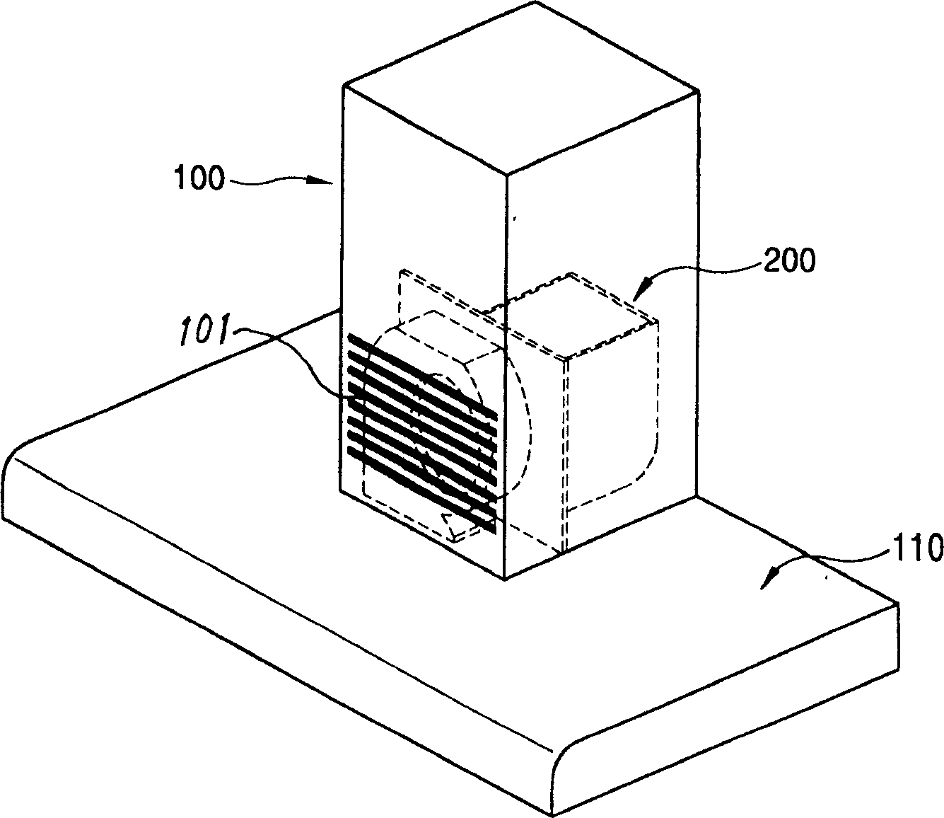
[0019] like image 3 , 4 , 5, the present invention includes, the vertical exhaust pipe 100 that is arranged on the ceiling to discharge the indoor air upwards, and the horizontal exhaust pipe 110 that is formed in the bottom of the vertical exhaust pipe 100 and is connected as a whole, is arranged on The interior of the vertical exhaust duct 100, the exhaust fan 210 that sucks in indoor air and discharges it upward, sucks the indoor air from the inflow port 101 formed in the middle of the vertical exhaust duct 100, and sends the sucked indoor air from the horizontal exhaust duct in order to prevent the diffusion of pollutants. The return fan 220 discharged under 110; the discharge fan 210 and the return fan 220 driven by the same motor in the same fan casing 201 together form the oil suction fan 200; it is arranged inside the horizontal exhaust duct 110 and distinguishes the h...


PUM


Abstract

The present invention discloses a kitchen ventilator. It includes vertical exhaust pipeline set on the ceiling board, horizontal exhaust pipeline positioned in the lower portion of vertical exhaust pipeline, connected together with it and formed into one body, exhaust fan set in the interior of vertical exhaust pipeline and reflux fan for sucking indoor air from flow inlet formed in the middle of vertical exhaust pipeline and discharging it. In same fan machine shell the exhaust fan and reflux fan are driven by same motor and formed into the ventilator fan. In the interior of horizontal exhaust pipeline a guide vane and an air exhaust channel are set, the lower portion of air exhaust channel is equipped with oil filter.

Description

technical field [0001] The invention belongs to a kitchen range hood device, in particular to an exhaust fan which uses the same motor to drive the main function in the kitchen range hood and discharge indoor air to the outside, and to return the indoor air to prevent pollutants Diffuse return fan for kitchen range hoods. Background technique [0002] Generally speaking, when cooking on a stove in a family kitchen or a commercial kitchen, pollutants such as high-temperature heat, smoke, odor, oil and gas will be generated, and these pollutants will spread to the kitchen or indoors under the action of high-temperature heat. Therefore, a range hood is generally installed above the stove and a pipe is connected on the outside, and the pollutants generated during cooking are discharged outside under the action of the fan. However, the range hood in the prior art has low efficiency, high noise, and poor air purification effect, causing more and more noise pollution. Especially ...

Claims


Application Information

Patent Timeline
IPC IPC(8): F24C15/20
Inventor 白丞祚孙尙范李制俊宋圣培
Owner LG ELECTRONICS (TIANJIN) APPLIANCES CO LTD
Why Eureka
Try Eureka