Remote observation system and method thereof

A remote observation and image signal technology, applied in closed-circuit television systems, control/regulation systems, instruments, etc., can solve problems such as power consumption and increased costs

Inactive Publication Date: 2006-03-29
LG ELECTRONICS INC
View PDF0 Cites 17 Cited by
  • Summary
  • Abstract
  • Description
  • Claims
  • Application Information

AI Technical Summary

Problems solved by technology

However, this method is not only costly but also very power consuming as the CCTV cameras need to be turned on all the time

Method used


Image

  • Remote observation system and method thereof
  • Remote observation system and method thereof

Examples


Embodiment Construction

[0015] Reference will now be made in detail to the preferred embodiments of the invention, examples of which are illustrated in the accompanying drawings.

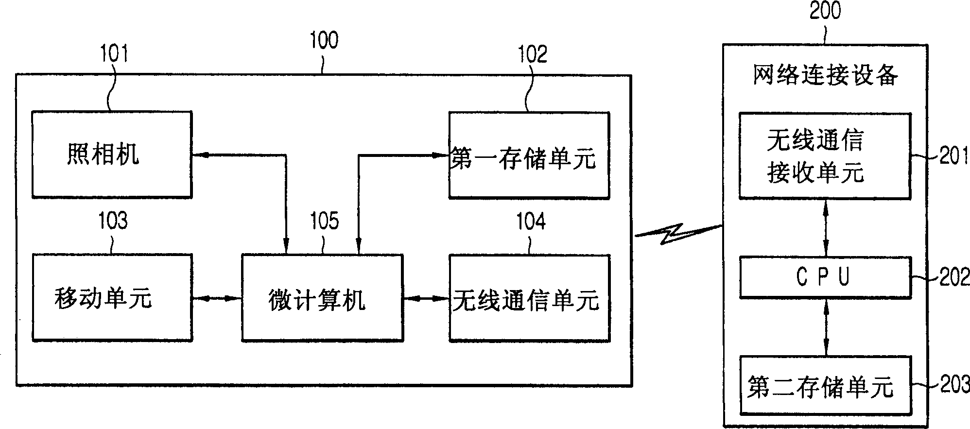
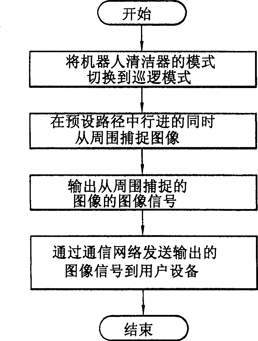
[0016] Hereinafter, the preferred embodiment of the remote observation system and method thereof according to the present invention can eliminate the blind spot of observation and enhance the convenience of the user by monitoring the situation of a specific space, such as a home, in real time through a mobile robot such as a robot cleaner from the outside by the user , and in addition, by the user monitoring a specific space in real time from the outside through a mobile robot such as a robot cleaner, such as the entire area of ​​a home, the cost of installing a CCTV camera for eliminating observation blind spots and the power consumption of a CCTV camera can be reduced, as follows refer to figure 1 with 2 The remote observation system and its method are described in detail.

[0017] First, the present invention is descr...


PUM


Abstract

A remote observation system and a method thereof includes: a robot cleaner for capturing images from the surroundings of a preset patrol path while traveling the preset patrol path and outputting image signals of the images captured from the surroundings when a mode of the robot cleaner is switched to the patrol mode by user's input signal; and a network connection device for transmitting the image signals outputted from the robot cleaner to user equipment through a communications network.

Description

technical field [0001] The present invention relates to a remote viewing system and method thereof, and more particularly, to a remote viewing system using a mobile robot such as a robot cleaner. Background technique [0002] Generally, a mobile robot, especially a robot cleaner, is used to automatically clean the area to be cleaned by sucking foreign substances such as dust from the lower surface while moving on its own indoors, such as a living room, bedroom, etc., without the need to Device operated by the user. [0003] In existing remote viewing camera systems using CCTV (Closed Circuit Television), usually the CCTV cameras are fixedly positioned. Even though the location of the CCTV camera can be controlled remotely, the control of the CCTV camera should be operated manually. [0004] Therefore, in the existing remote viewing camera system using CCTV (Closed Circuit Television), it is possible to photograph the area where the CCTV camera is installed, but the area wh...

Claims


Application Information

Patent Timeline
Patent Type & Authority Applications(China)
IPC IPC(8): H04N7/18
CPCH04N7/181H04N7/185G05D1/0246G05D2201/0209G05D2201/0215H04N7/18
Inventor 柳湖善禹春圭
Owner LG ELECTRONICS INC
Why Eureka
Try Eureka