
Safety alcohol burner

A technology of alcohol lamps and alcohol, which is applied in the field of alcohol lamps, can solve problems such as the inability of alcohol to flow out, and achieve the effect of eliminating fire hazards and preventing the outflow of alcohol

Inactive Publication Date: 2006-04-19
梁伟
View PDF0 Cites 7 Cited by
  • Summary
  • Abstract
  • Description
  • Claims
  • Application Information

AI Technical Summary

Problems solved by technology

None of the currently known alcohol lamps can achieve the effect that alcohol cannot flow out from any of the aforementioned paths after it is overturned

Method used


Image

  • Safety alcohol burner

Examples


Embodiment Construction

[0009] The present invention will be further described below in conjunction with the accompanying drawings and embodiments.

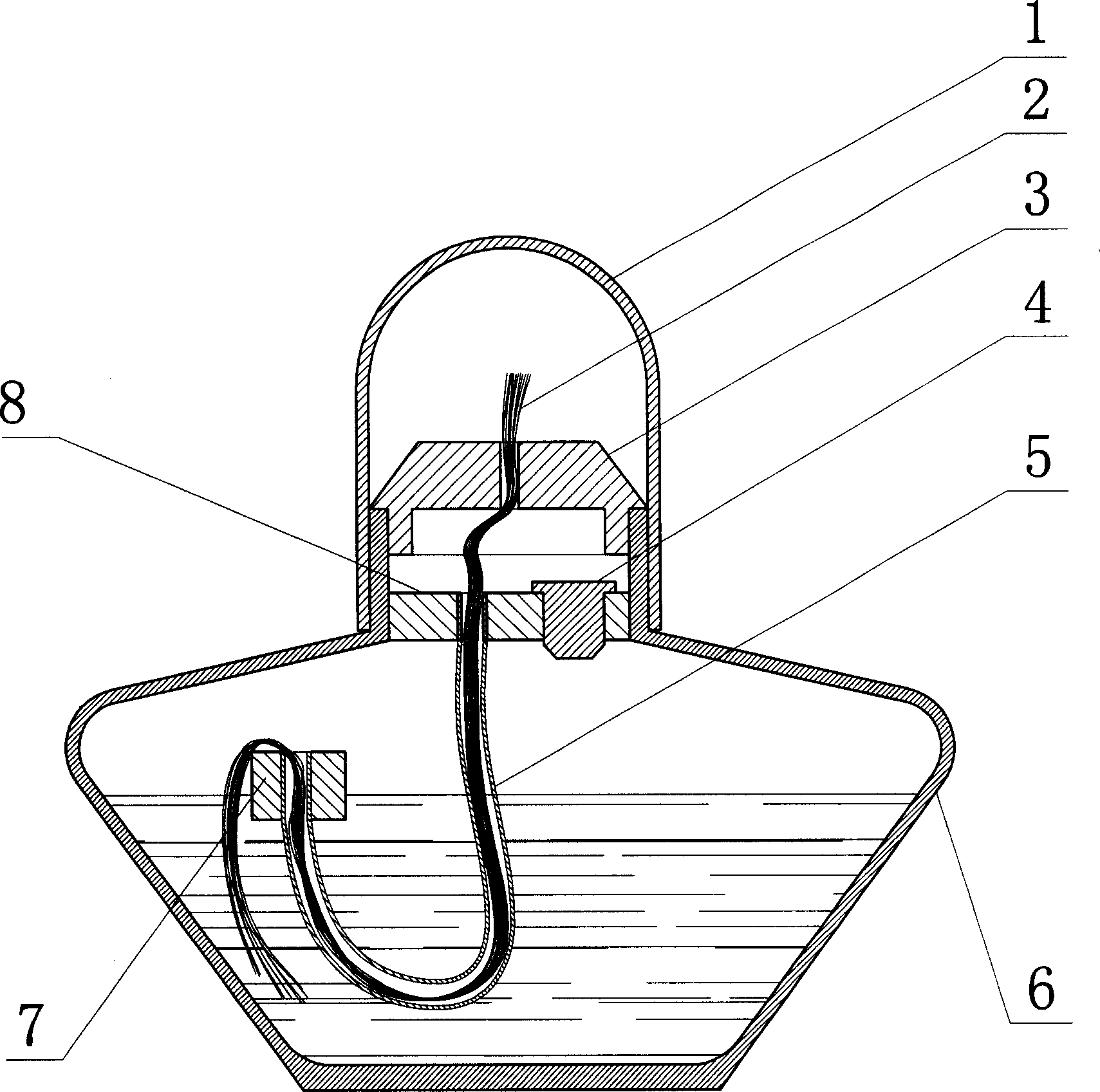
[0010] The safety alcohol lamp of the present invention is composed of a lamp cap 1, a wick 2, a ceramic wick seat with holes 3, an alcohol inlet plug 4, a wick film tube 5, a lamp bottle 6, a floating block 7 and an inner plug 8. The perforated ceramic wick holder 3 is placed at the opening of the lamp bottle 6, and the cylindrical engineering plastic inner plug 8 is located at the neck of the lamp bottle 6, and it forms a static fit relationship with the neck of the lamp bottle 6. The wick hole and the alcohol inlet hole required for adding alcohol. Alcohol inlet plug 4 is the cylindrical engineering plastics plug of chamfering on the lower edge of the band cap on the upper edge, which is used to seal the alcohol in the bottle. Floating block 7 is a polyethylene foam block, and its center has a wick hole. The diameter of inner plug wick hole, floati...


PUM


Abstract

A safety alcohol lamp consists of crown top, lamp wick, ceramic lamp wick seat with hole, alcohol inlet plug, lamp wick film tube, lamp bottle, floating block and internal plug. It features that lamp bottle is sealed by internal plug and lampwick is separated from alcohol part by said file tube as well as opening of said film tube is raised all the time by floating block to let said film tube opening be higher than alcohol level so alcohol can not be flowed out from lamp wick through said film tube although alcohol lamp is fallen down.

Description

1. Technical field [0001] The invention relates to an alcohol lamp, in particular to a safety alcohol lamp which is safe to use and reduces fire hazards. 2. Background technology [0002] During the use of the existing alcohol lamp, once the lamp bottle is overturned, the alcohol will flow out and there is a danger of causing a fire. There are two paths for the alcohol to flow out from the lamp bottle: one is that the alcohol flows out from the bottle mouth due to the separation of the lamp bottle and the lamp holder; the other is that the alcohol flows out from the wick hole along the wick. None of the present known alcohol lamps can reach the effect that alcohol can not flow out from any of the aforementioned paths after it falls over. 3. Contents of the invention [0003] In order to solve the deficiencies of the prior art, the present invention provides a safety alcohol lamp that can effectively prevent the alcohol from leaking out of the overturned alcohol lamp. [...

Claims


Application Information

Patent Timeline
IPC IPC(8): F23D3/26
Inventor 梁伟
Owner 梁伟
Learn More