Refrigerator
A technology for refrigerators and coolers, used in defrosting, household appliances, refrigeration and liquefaction, etc., can solve problems such as expansion and contraction of insulating materials, the influence of control circuit boards, and leakage of electricity, etc. are not considered.
- Summary
- Abstract
- Description
- Claims
- Application Information
AI Technical Summary
Problems solved by technology
Method used
Image
Examples
Embodiment 1
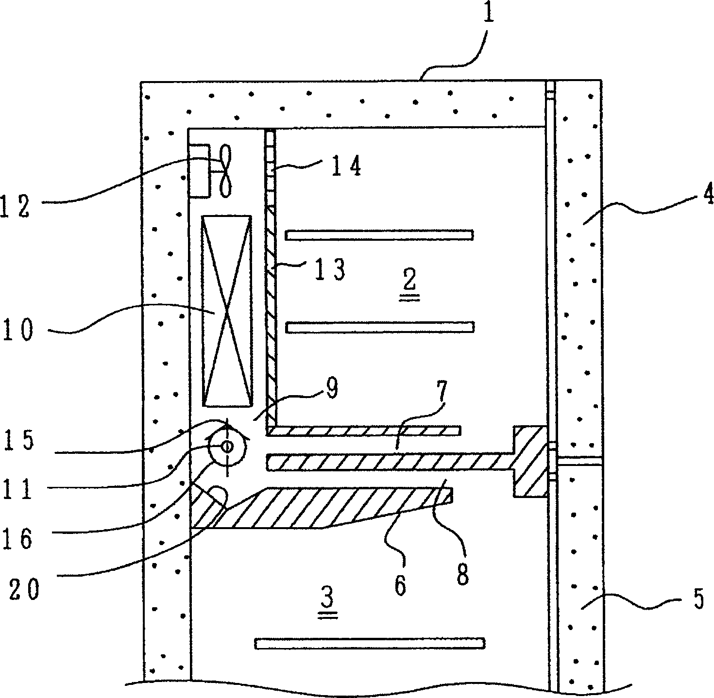
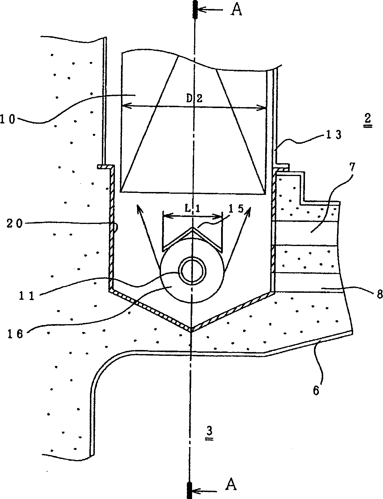
[0052] First, use figure 1 ~ Figure 4 illustrates the structure of the refrigerator. The refrigerator main body 1 has a freezer compartment 2 and a refrigerator compartment 3 inside it. In front of the freezer compartment 2 there is a freezer door 4 for closing the opening, and in front of the refrigerator compartment 3 there is a refrigerator door 5 for closing the opening. Between the freezing chamber 2 and the refrigerating chamber 3, there is an intermediate partition 6 which separates the two chambers. The duct 7 that goes to the cooler described later, and the duct 8 that returns the cold air after heat exchange with the food in the refrigerating chamber 3 to the cooler.
[0053] At the back of the freezer compartment 2, a cooler compartment 9 partitioned by a partition 13 is arranged. In this cooler compartment 9, a cooler 10, a defrosting heater 11, and a cooling air circulation fan 12 are provided. In this embodiment, the defrosting heater 11 is arranged below the...
Embodiment 2
[0073] Next, use Figure 5 and Figure 6 Example 2 will be described.
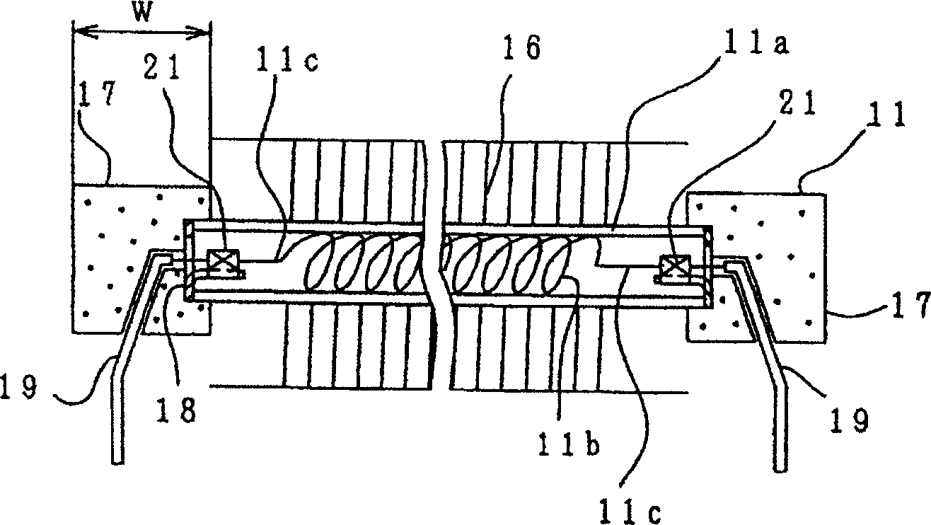
[0074] First, in Figure 5 Among them, the reference numeral 17 is a rubber plug, the reference numeral 16 is a cooling fin, and the reference numeral 11a is a glass tube. One end face in the width direction of the above-mentioned heat dissipation fin 16 is wound to perpendicularly intersect with the glass tube 11a. In order to absorb the difference in natural curvature, a diameter-reduction is provided near the inner side of the above-mentioned heat dissipation fin (on the side of the glass tube). Part 16c, and the side opposite to the glass tube is made into a plane.
[0075] As shown in the figure, the cooling fins 16 are wound around the glass tube 11 a between the rubber plugs 17 . In other words, the cooling fins 16 are provided over the entire length of the glass tube 11a between the rubber plugs at both ends of the glass tube 11a.
[0076] Reference numeral 16b is a bent portion provided at th...
Embodiment 3
[0086] Next, use Figure 7 ~ Figure 9 A third embodiment of the present invention will be described.
[0087] In the figure, the numeral 10 is a cooler, the numeral 11 is a defrosting heater, the numeral 11a is a glass tube, the numeral 11b is a heating wire, the numeral 15 is an upper cover, the numeral 15a is a fixed part of the upper cover 15, and the numeral 15b is each The connecting part where the fixed parts are connected, the number 16 is the heat dissipation fin, the number 17 is the rubber plug, the number 20 is the water tank, the number 20a is the water outlet of the water tank, the number 20b is the metal plate (aluminum plate) for heating the water tank, and the number 19 is Reference numeral 20c is a support leg for supporting the heater for defrosting on the water tank 20 as a lead wire for supplying power to the heating wire 11b.
[0088] Figure 8 , the upper cover 15 is close to or in contact with the cooling fins 16 . The upper cover 15 is close to or in...
PUM
| Property | Measurement | Unit |
|---|---|---|
| Outer diameter | aaaaa | aaaaa |
| The inside diameter of | aaaaa | aaaaa |
| Outer diameter | aaaaa | aaaaa |
Abstract
Description
Claims
Application Information
 - R&D
- Intellectual Property
- Life Sciences
- Materials
- Tech Scout
- Unparalleled Data Quality
- Higher Quality Content
- 60% Fewer Hallucinations
Browse by: Latest US Patents, China's latest patents, Technical Efficacy Thesaurus, Application Domain, Technology Topic, Popular Technical Reports.
© 2025 PatSnap. All rights reserved.Legal|Privacy policy|Modern Slavery Act Transparency Statement|Sitemap|About US| Contact US: help@patsnap.com


