Supercharge Your Innovation With Domain-Expert AI Agents!

Antenna device and antenna device manufacturing method

一种天线装置、导线的技术,应用在天线、天线耦合、天线零部件等方向

Inactive Publication Date: 2006-04-19
SONY GRP CORP
View PDF1 Cites 1 Cited by
  • Summary
  • Abstract
  • Description
  • Claims
  • Application Information

AI Technical Summary

Problems solved by technology

Therefore, when Image 6 This is especially a problem when the illustrated antenna 30 is an AM antenna, which tends to pick up interfering noise

Method used


Image

  • Antenna device and antenna device manufacturing method
  • Antenna device and antenna device manufacturing method
  • Antenna device and antenna device manufacturing method

Examples


Embodiment Construction

[0024] Embodiments of the present invention will now be described sequentially below. This embodiment will be described taking a case where the loop antenna is an AM antenna device corresponding to AM broadcasting as an example.

[0025] Here, in the case of applying a countermeasure against noise to a loop antenna type AM antenna, it can be considered as Figure 5A with 5B configuration shown.

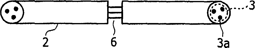
[0026] Figure 5A is a view from the front of the AM antenna device 1A. Figure 5B showing along Figure 5A A profile of the line A-A.

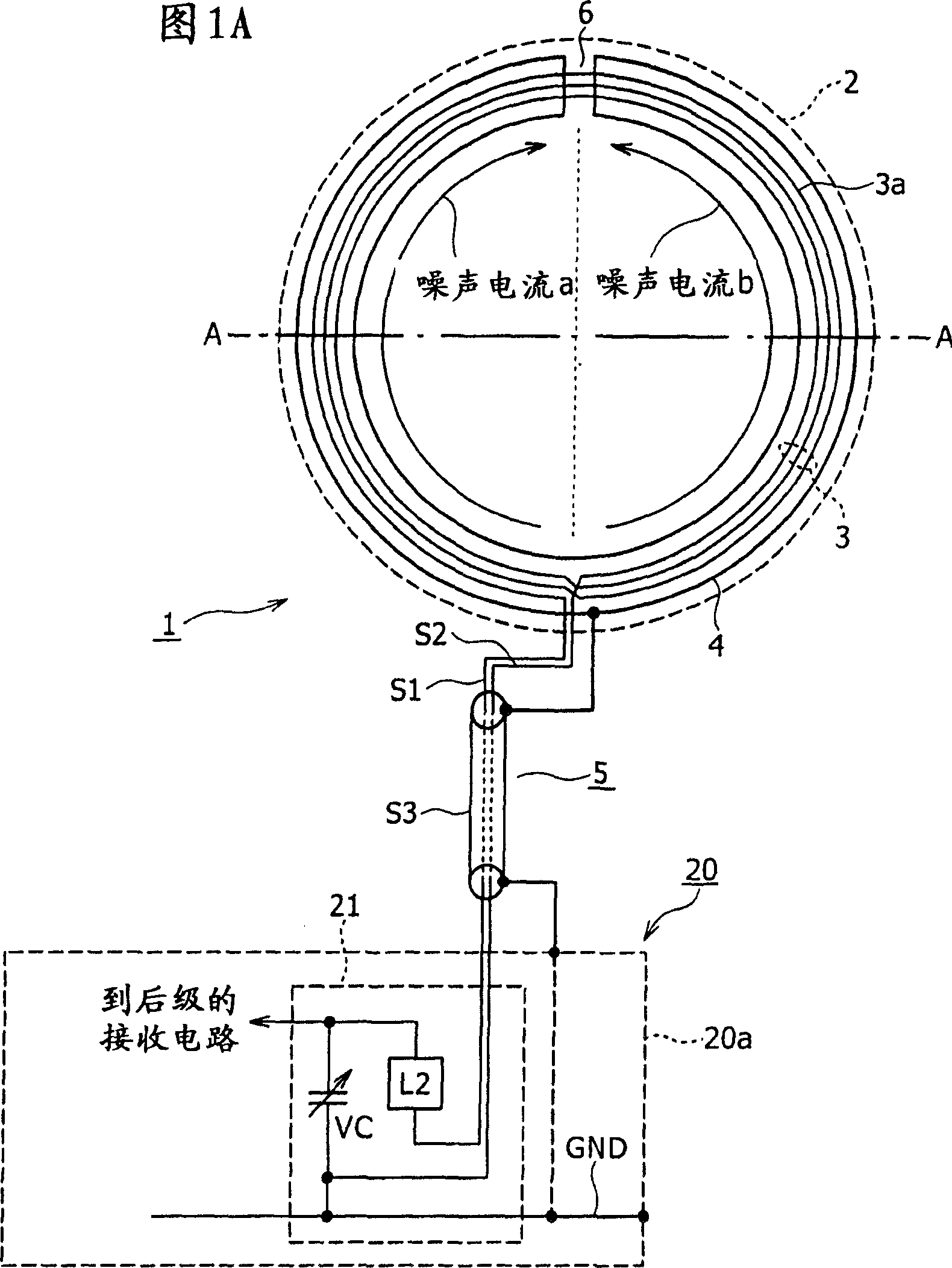
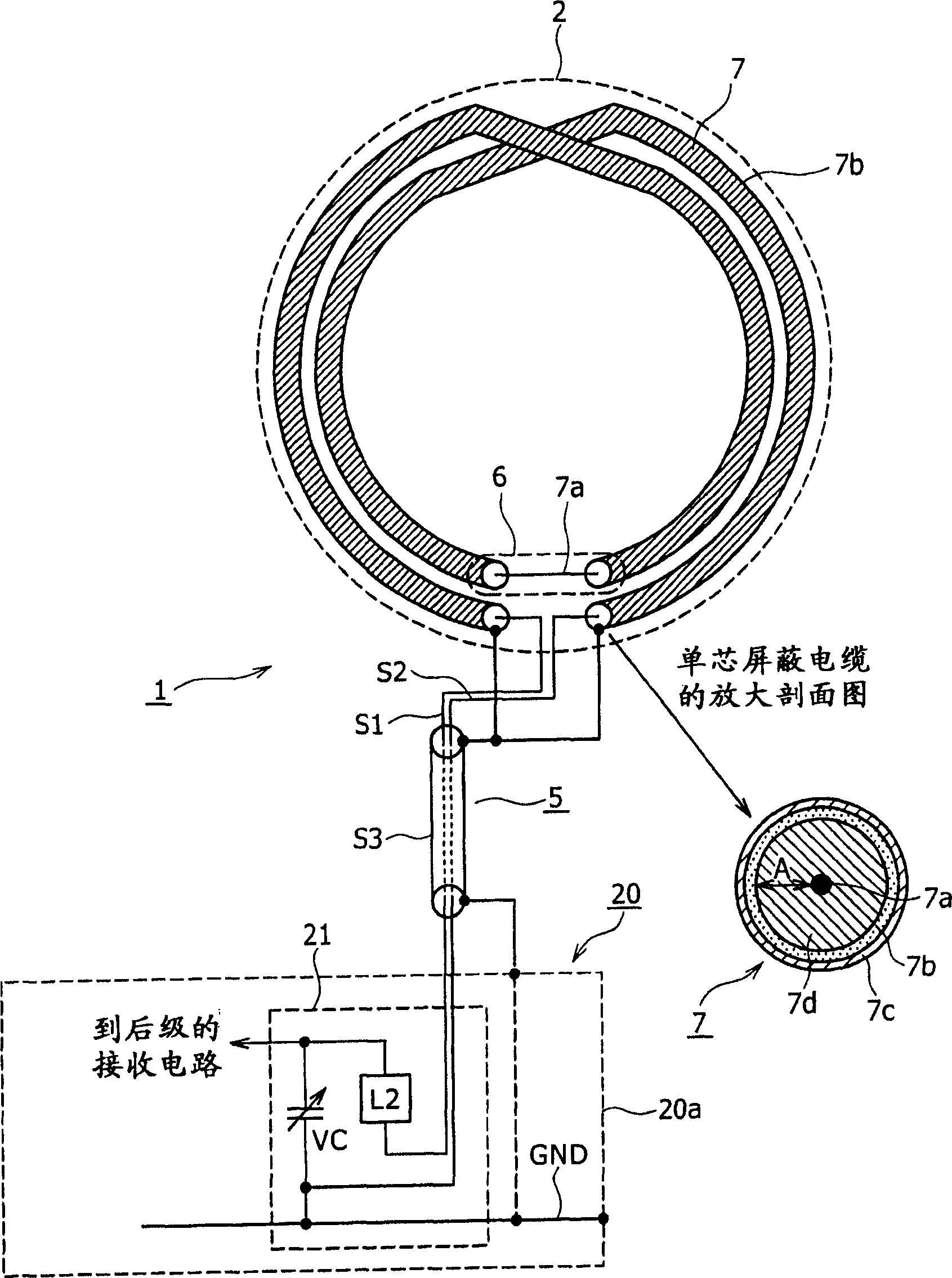
[0027] Such as Figure 5A with 5B As shown, the AM antenna device 1A is composed of a loop antenna section 2 including a loop conductor section 3 and a shielded pipe member 4, and a feeder line 5A for connecting the loop antenna section 2 to the AV The receiving circuit side of the device 20 to provide power.

[0028] In the loop antenna section 2, the loop conductor section 3 is formed by winding a wire 3a in a loop by a desired number of t...


PUM


Abstract

An antenna device having a loop antenna with a good noise resistance performance. The loop antenna is composed of a loop conductor section formed of a looped conductive wire and a shield member covering the loop conductor section. The antenna device is connected to a receiving circuit at two terminals. The loop conductor section has a non-covered portion corresponding to the portion of the conductive wire including the reference position with respect to which the two terminals are symmetrical. Thus, a balancing shield structure is created. A line for connecting one end of the conductive wire to the ground potential and a line for connecting the shield member to the ground potential are separately provided. The voltage drop due to the common impedance is hardly received by the antenna.

Description

technical field [0001] The invention relates to an antenna arrangement comprising a so-called loop antenna having a loop shape, and to a method of manufacturing such an antenna arrangement. Background technique [0002] In AV equipment in recent years, switching power supply circuits are mounted in many cases, for example, to reduce power consumption and size. Switching power supply circuits are known to generate switching noise at relatively high frequencies. In addition, in AV digital equipment typified by, for example, CD players, high-frequency noise is generated from digital circuits. In short, in AV equipment and the like in recent years, there is a tendency for high-frequency noise such as so-called in-device noise to increase. [0003] AV equipment that incorporates radio tuners has spread widely. When such an AV device with a radio tuner generates the above-mentioned in-device noise, an antenna for receiving radio broadcast waves suffers from the inconvenience th...

Claims


Application Information

Patent Timeline
Patent Type & Authority Applications(China)
IPC IPC(8): H01Q7/04H01P11/00H01Q1/52H01Q7/02
CPCH01Q7/04H01Q7/02H01Q1/526H01Q1/521H01Q1/40H01P11/001
Inventor 森冈进高野崇三枝繁
Owner SONY GRP CORP
Features
  • R&D
  • Intellectual Property
  • Life Sciences
  • Materials
  • Tech Scout
  • Unparalleled Data Quality
  • Higher Quality Content
  • 60% Fewer Hallucinations
Learn More