
Toroidal line filter and method of winding coil of toroidal line filter

A ring circuit and filter technology, applied in the direction of transformer/inductor coil/winding/connection, transformer/inductor core, transformer/inductor parts, etc.

Inactive Publication Date: 2006-04-26
HEWLETT PACKARD DEV CO LP
View PDF0 Cites 0 Cited by
  • Summary
  • Abstract
  • Description
  • Claims
  • Application Information

AI Technical Summary

Problems solved by technology

[0010] Therefore, the present invention is proposed to solve at least the above-mentioned problems and provide other advantages. It is an object of the present invention to provide a loop line filter having coils wound by different winding steps so as to pass Or the change of the area can improve the inductive characteristics of the specific frequency, so that the ring line filter can deal with the situation of poor EMI characteristics at the specific frequency without changing the line by adding any components such as inductors or capacitors

Method used


Image

  • Toroidal line filter and method of winding coil of toroidal line filter
  • Toroidal line filter and method of winding coil of toroidal line filter
  • Toroidal line filter and method of winding coil of toroidal line filter

Examples


Embodiment Construction

[0021] Hereinafter, exemplary embodiments of the present invention are described in more detail with reference to the accompanying drawings.

[0022] The matters described in the detailed description, such as detailed structures and elements, are provided to help a more complete understanding of the present invention. It is therefore evident that various changes and modifications of the embodiments described herein can be made without departing from the scope and spirit of the invention. Descriptions of well-known functions or constructions are omitted for clarity and conciseness.

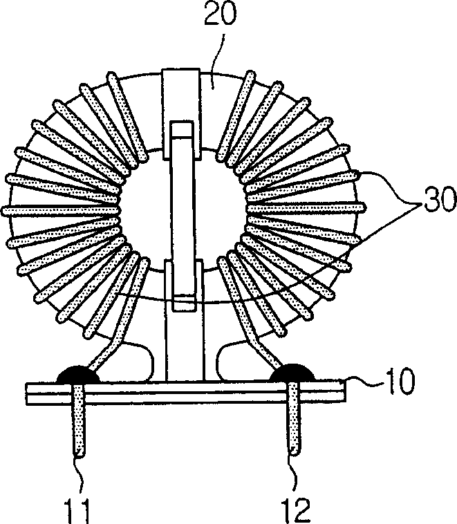
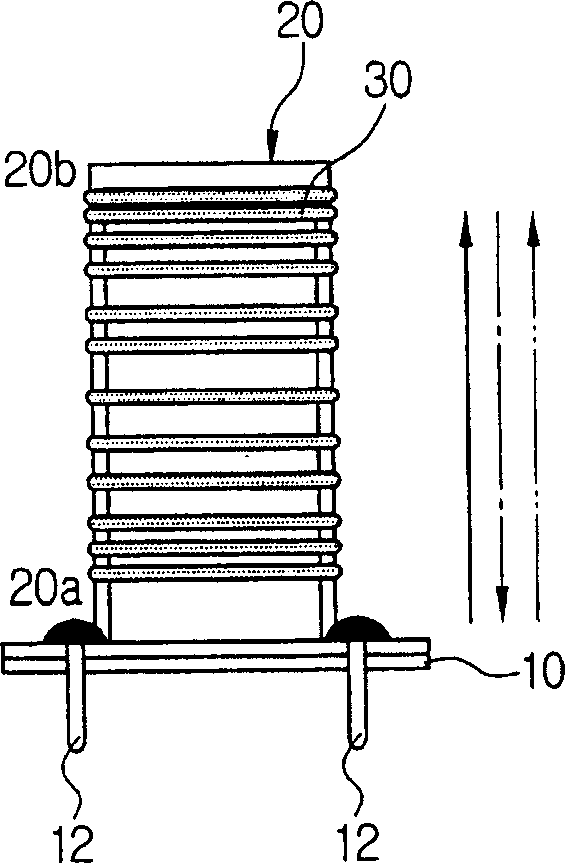
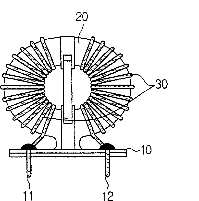
[0023] Such as Figure 2A and 2B Shown is the basic structure of the loop line filter constructed according to an embodiment of the present invention. A ring line filter according to an embodiment of the present invention includes a substrate 10, a ring core 20 supported on the base board 10, and a coil 30 wound on the ring core 20, which are the same as those in the structure of the above-menti...


PUM


Abstract

Disclosed is a loop line filter having coils wound through different winding steps, so that induction characteristics to specific frequencies can be improved by changing the current flow direction and / or area, whereby the loop line filter can compensate for specific frequencies. Poor EMI characteristics over frequency without adding additional components such as inductors or capacitors. The toroidal line filter includes a toroidal core and a coil wound around the toroidal core. The coil is constructed in such a way that the first coil is wound not the entire area but a specific partial area, and then the second coil is wound around the remaining area of ​​the annular core.

Description

technical field [0001] The present invention relates to a method of winding a loop line filter for use in the primary AC power supply terminals of a switched mode power supply (SMPS) for supplying power to printers or other electrical or electronic appliances to improve electromagnetic interference (EMI) characteristics. Background technique [0002] SMPS is a modular power supply, which is used to transform external power supply into a variety of electrical or electronic appliances including computers, televisions, video recorders, wireless communication equipment and so on. It is used to intermittently control high frequencies higher than the mains frequency by using the switching characteristics of semiconductors, and to prevent damage. The application of such SMPSs as main power supplies for electrical or electronic appliances is becoming more common because of their small size and high efficiency. [0003] Although such SMPSs have advantages of small size and light we...

Claims


Application Information

Patent Timeline
Patent Type & Authority Applications(China)
IPC IPC(8): H01F17/04H01F27/28H01F41/00
CPCH01F17/062H01F27/2823H03H2001/0092H01F41/082H01F27/24H01F27/306
Inventor 罗泰权吴哲宇
Owner HEWLETT PACKARD DEV CO LP
Learn More