Dynamic pressure bearing device

A hydrodynamic bearing and bearing technology, which is applied in sliding contact bearings, bearings, bearings in rotating motion, etc., can solve the problems of flow interference of lubricating fluid 120, and achieve the effect of reducing vibration and noise.

Active Publication Date: 2006-05-03
NIDEC CORP
View PDF0 Cites 15 Cited by
  • Summary
  • Abstract
  • Description
  • Claims
  • Application Information

AI Technical Summary

Problems solved by technology

Therefore, the flow of lubricating fluid 120 is disturbed

Method used


Image

  • Dynamic pressure bearing device
  • Dynamic pressure bearing device
  • Dynamic pressure bearing device

Examples


Embodiment Construction

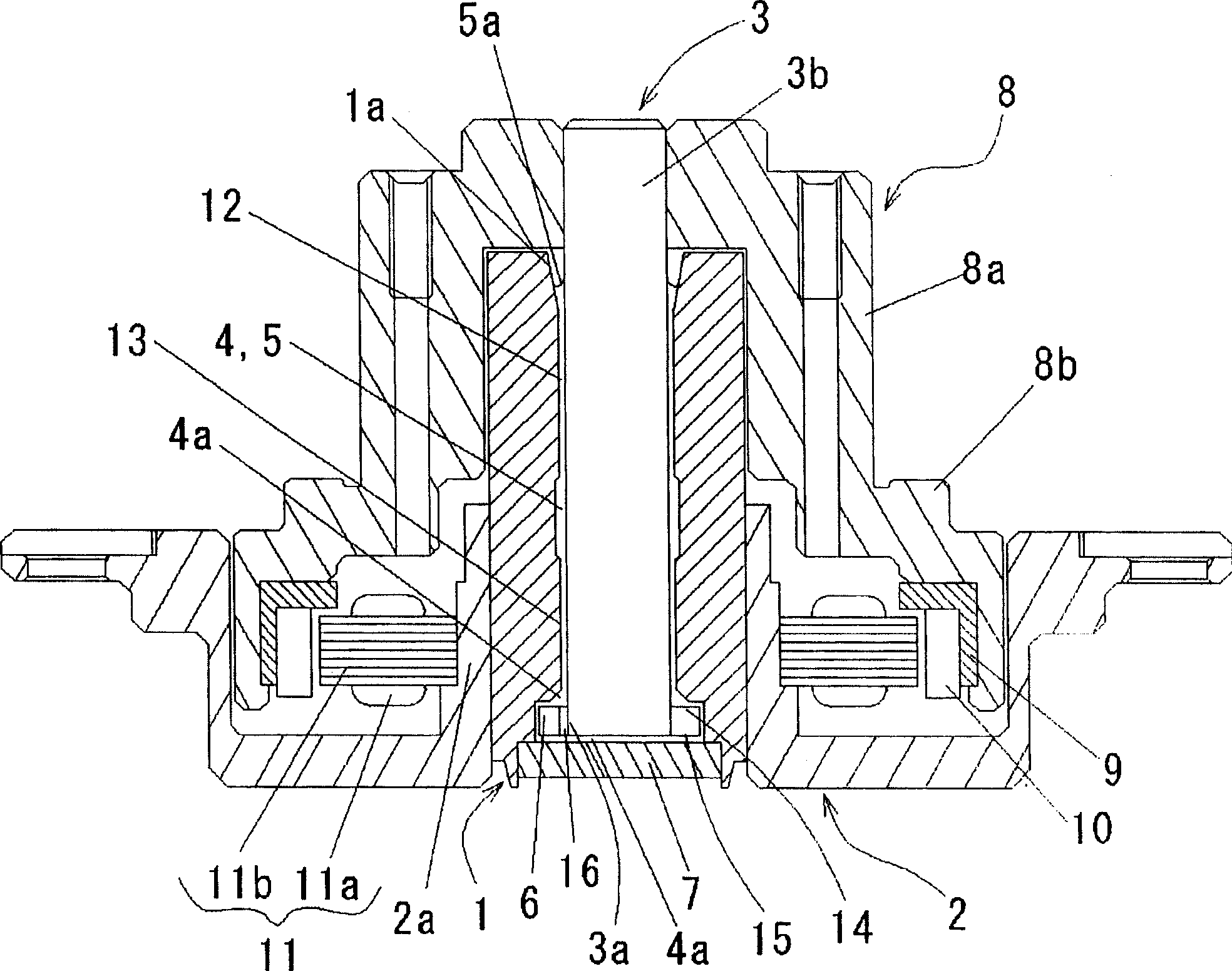
[0030] figure 1 A hard disk drive spindle motor using a fluid dynamic pressure bearing device, which is one configuration of an example of a fluid dynamic pressure bearing device related to the present invention, is shown in . figure 1 is a view of the section in the direction of the axis of rotation.

[0031] will refer to figure 1 An overall description of the spindle motor used to drive the hard disk is given.

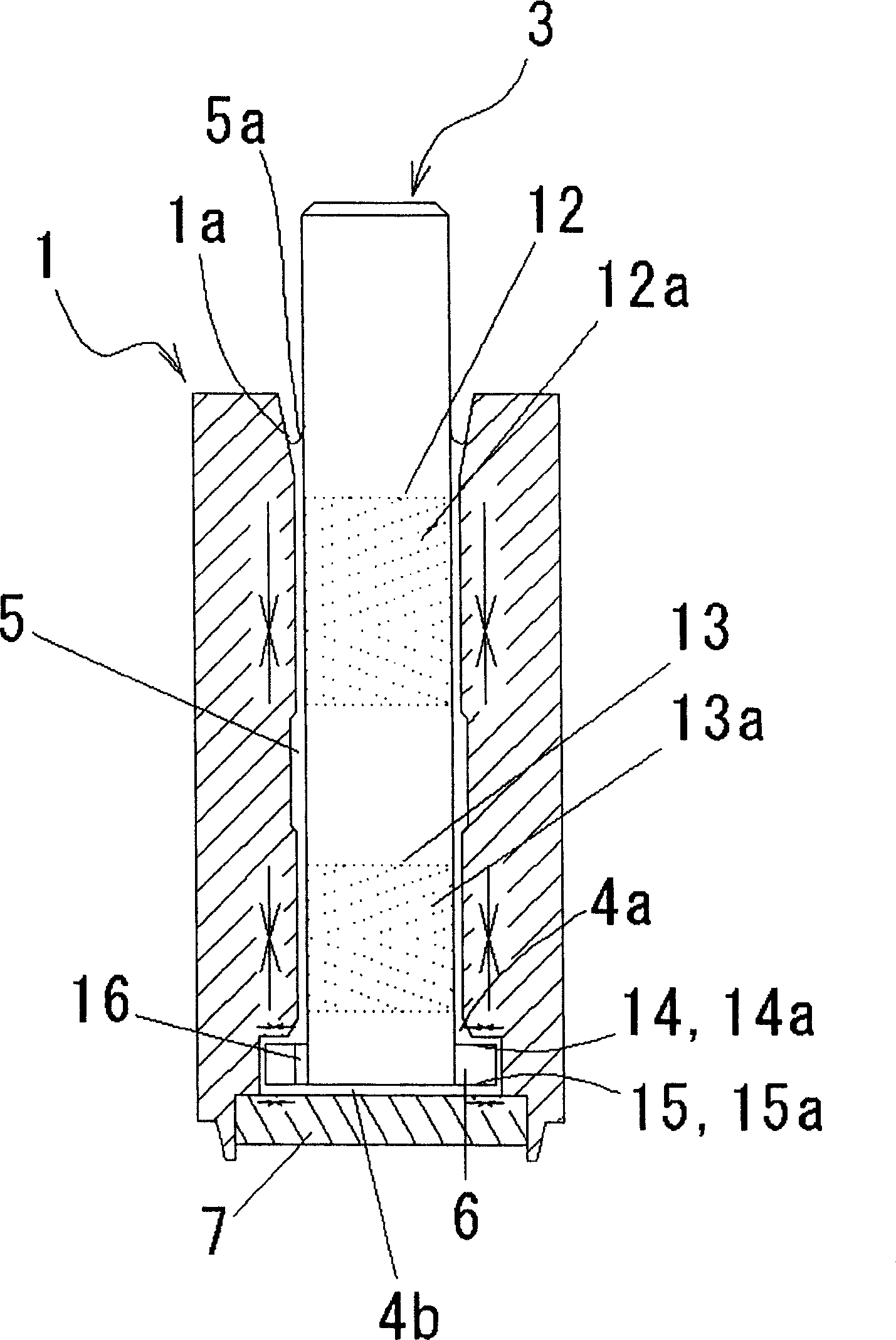
[0032] The bearing sleeve 1 has a hollow cylindrical shape, and the cylindrical housing 2 with the bottom is fixed to the outer circumference of the bearing sleeve 1 by bonding or gluing, for example, which can directly connect the spindle motor to the hard disk drive with screws or the like. the underside of the surface. The shaft 3 as a rotating shaft is inserted into the bearing sleeve 1 with a minute gap 4 interposed between the shaft 3 and the bearing sleeve 1 on the inner circumferential surface of the bearing sleeve 1 . Lubricating fluid 5 , such as oi...


PUM


Abstract

In the tiny gap (4) between the underside radial bearing part (13) and the top surface thrust bearing part (15) of the shaft (3), thrust plate (6) and bearing sleeve (1) In the wider flow channel (4a) surrounded by the circumferential corner part (1c), chamfering is performed at the inner circumferential corner part (1c) of the bearing sleeve (1), wherein the wider flow channel (4a) is in the radial direction of rotation The width is formed wider than that of the communication hole (16) located below the wider flow passage (4a) in the radial direction of rotation, thereby smoothing the flow of the lubricating fluid (5) from the communication hole The holes (16) flow into the wider flow channel (4a).

Description

technical field [0001] The present invention relates to a hydrodynamic bearing device in which a bearing member and a shaft member are suspended so as to be relatively rotatable by dynamic pressure generated in a lubricating fluid. Background technique [0002] In recent years, various dynamic pressure bearing devices have been proposed for supporting various rotating bodies such as high-speed rotating magnetic disks, polygon mirrors, and optical disks. For example in Figure 13 , a hydrodynamic bearing device is shown mounted on a spindle motor for a hard disk drive. Figure 13 The arrow marks in the middle solid line indicate the direction of action of the pressure in the lubricating fluid within the bearing section. [0003] like Figure 13 As shown, the dynamic pressure bearing device is configured such that the rotating shaft 110 is inserted in the bearing sleeve 100 in a freely rotatable manner. The lubricating fluid 120 , such as oil, is injected into a minute gap be...

Claims


Application Information

Patent Timeline
IPC IPC(8): F16C33/10F16C17/10
Inventor 安藤博典竹村健太郎三上寿人
Owner NIDEC CORP
Why Eureka
Try Eureka