
Electronic component mounting device

A technology of electronic component installation and electronic components, applied in the direction of electrical components, electrical components, etc., can solve the problems of no detection, no data association, etc., and achieve the effect of quality improvement and reduction of poor loading

Active Publication Date: 2006-05-03
JUKI CORP
View PDF1 Cites 5 Cited by
  • Summary
  • Abstract
  • Description
  • Claims
  • Application Information

AI Technical Summary

Problems solved by technology

However, data related to electronic components in each measurement timing is not correlated
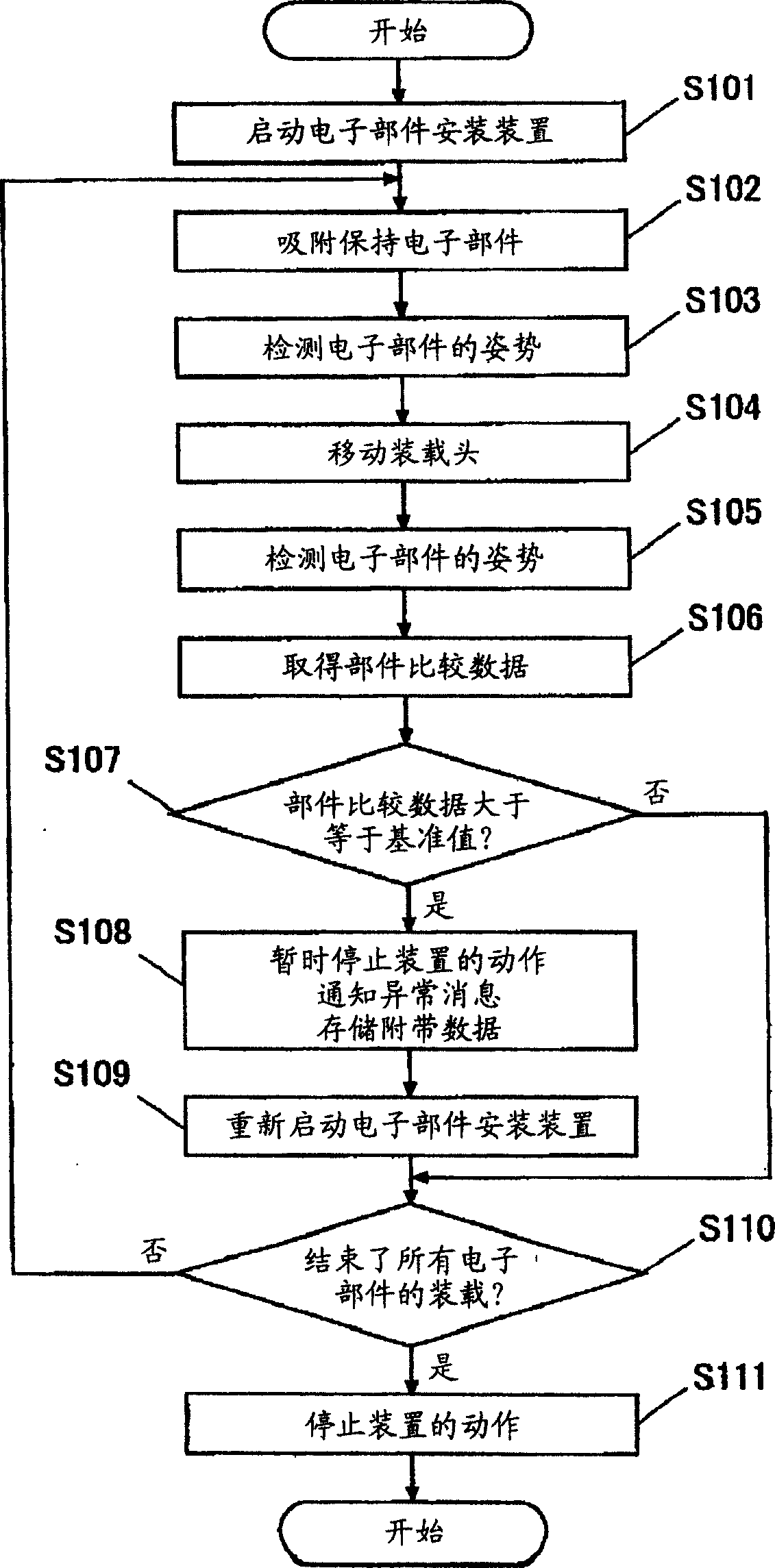
[0007] That is, the data related to the electronic component acquired at the timing at which the suction nozzle sucks and holds the electronic component and the timing at which the mounting head having the suction nozzle holding the electronic component moves with respect to the substrate after that is not correlated, there is no Detects state changes such as the posture of the electronic component held by the suction nozzle during the process (the process in which the loading head with the suction nozzle moves after the suction nozzle suctions and holds the electronic component)

Method used


Image

  • Electronic component mounting device
  • Electronic component mounting device
  • Electronic component mounting device

Examples


Embodiment Construction

[0048] Hereinafter, embodiments of the present invention will be described in detail.

[0049] The electronic component mounting apparatus of the present invention is an apparatus for loading and mounting electronic components supplied from a component supply unit (electronic component feeder) on predetermined positions on a board.

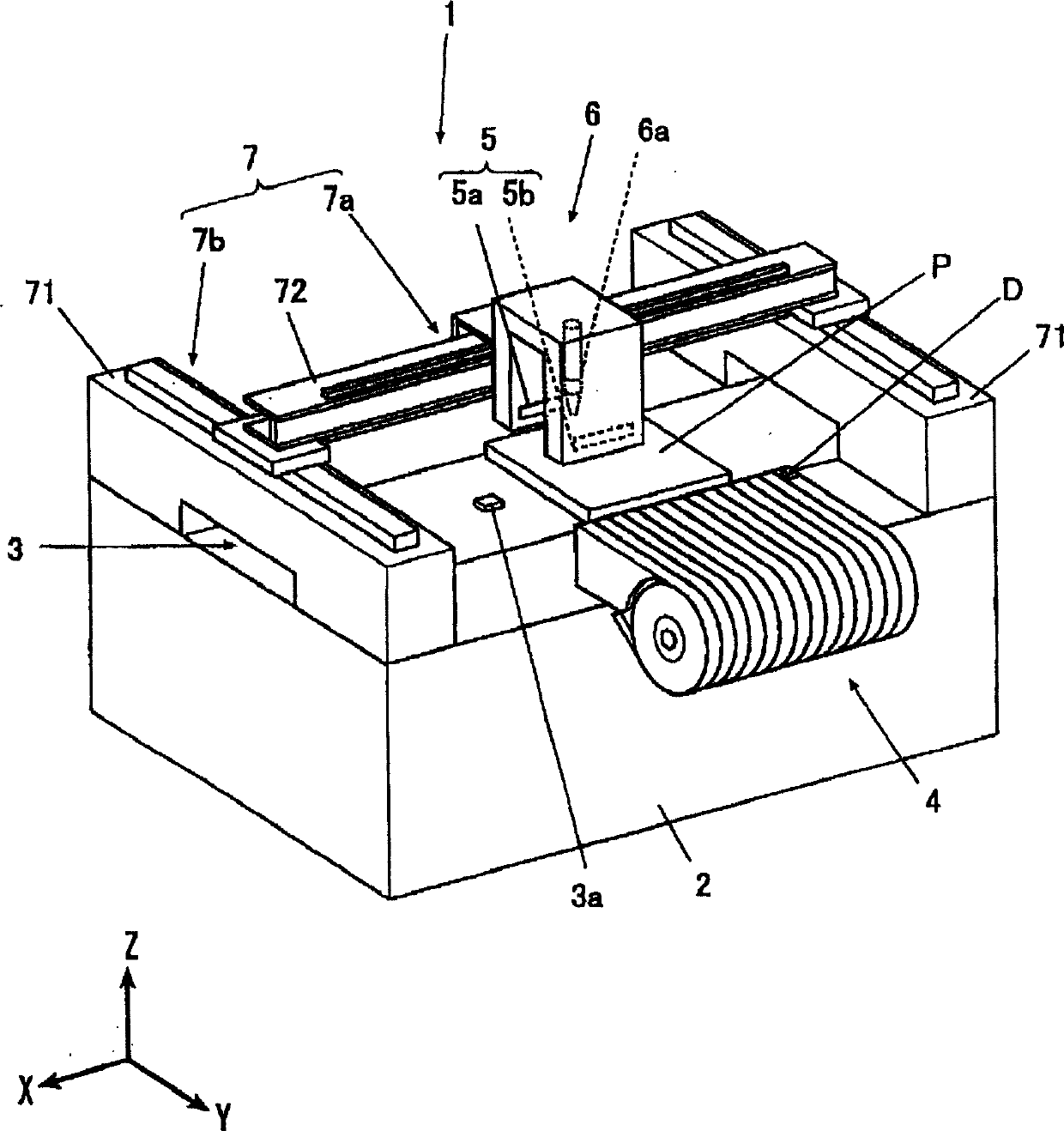
[0050] Here, in the electronic component mounting apparatus, the direction in which the substrate P is conveyed from the previous process to the subsequent process is defined as the X-axis direction, and the direction perpendicular to the X-axis direction is defined as the Y-axis direction. The direction in which both directions are perpendicular is defined as the Z-axis direction.

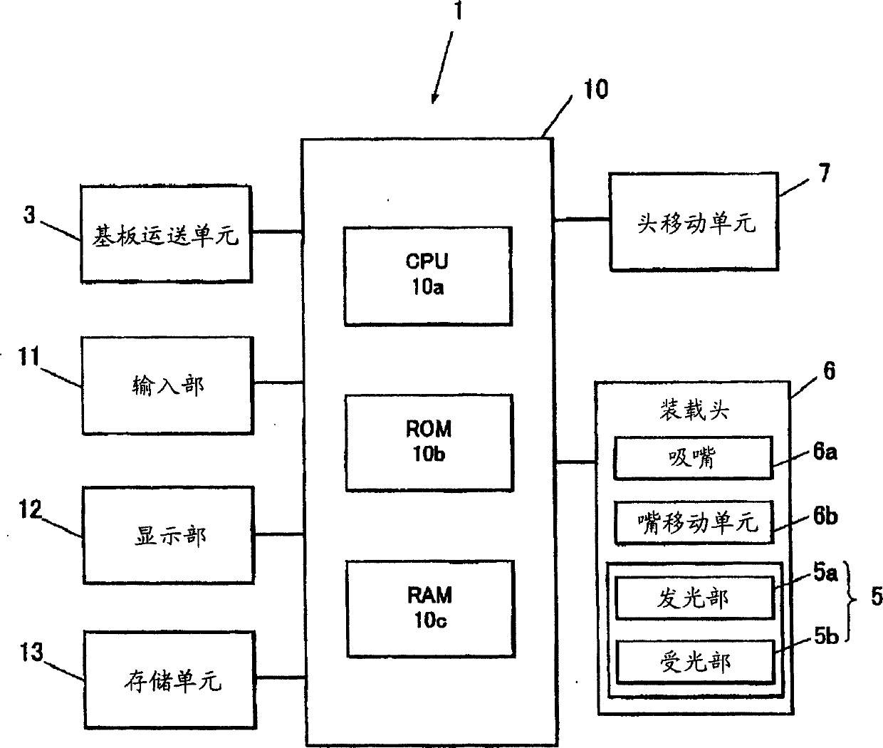
[0051] FIG. 1 is a perspective view of an electronic component mounting apparatus 1 , and FIG. 2 is a block diagram showing a main part configuration of the electronic component mounting apparatus 1 .

[0052] As shown in Fig. 1 and Fig. 2, the electronic component m...


PUM


Abstract

An electronic component mounting apparatus improves the quality of a substrate on which electronic components are mounted according to a state change of an electronic component held by a suction nozzle. In the electronic component mounting apparatus (1), after the suction nozzle (6a) holds the electronic component (D), at a plurality of timings while the loading head (6) having the suction nozzle (6a) moves relative to the substrate (P) , compare the postures of the electronic components (D) in multiple timings detected by the laser recognition unit (5), and obtain component comparison data related to the different postures of these electronic components (D), and compare the component comparison data Compare with predetermined benchmark value. When the control unit (10) as the judging unit judges that the component comparison data is greater than or equal to the reference value, the displacement of the electronic component (D) held by the suction nozzle (6a) is large, and it is often loaded on the substrate (P ) on the board (P), a failure occurs, so the operation of loading the electronic component (D) held by the suction nozzle (6a) on the substrate (P) is stopped.

Description

technical field [0001] The present invention relates to an electronic component mounting device. Background technique [0002] Conventionally, an electronic component mounting apparatus is known as an apparatus for mounting electronic components on a substrate. The electronic component mounting apparatus sucks and holds a plurality of electronic components supplied from a component supply unit by using a suction nozzle provided on a loading head. Transfer to base plate for loading and installation. [0003] In such an electronic component mounting apparatus, after the suction nozzle sucks and holds the electronic component from the component supply unit, and in order to mount the electronic component on the substrate, the mounting head having the suction nozzle holding the electronic component moves relative to the substrate. At each timing of , the presence or absence of an electronic component held by the tip of the suction nozzle is detected. In addition, an electronic ...

Claims


Application Information

Patent Timeline
Patent Type & Authority Applications(China)
IPC IPC(8): H05K13/00
Inventor 黑田洁
Owner JUKI CORP
Learn More