Plane framework supporting structure capable of steel charge expansion

An inflatable deployment and support structure technology, which is applied to the support structure of photovoltaic modules, electrical components, antenna supports/mounting devices, etc., can solve the problems of poor reliability of deployment, heavy overall weight, and low folding efficiency, and achieve light overall weight , simple structure and high folding efficiency

Inactive Publication Date: 2006-05-10
HARBIN INST OF TECH
View PDF0 Cites 26 Cited by
  • Summary
  • Abstract
  • Description
  • Claims
  • Application Information

AI Technical Summary

Problems solved by technology

[0003] The purpose of the present invention is to solve the problems of complex structure, easy failure, poor deployment reliability, heavy overall weight and low folding efficiency in use of the existing planar frame support structure of solar panels and planar antennas due to mechanical deployment. A planar frame support structure that can be rigidified and inflated

Method used


Image

  • Plane framework supporting structure capable of steel charge expansion
  • Plane framework supporting structure capable of steel charge expansion
  • Plane framework supporting structure capable of steel charge expansion

Examples


specific Embodiment approach 1

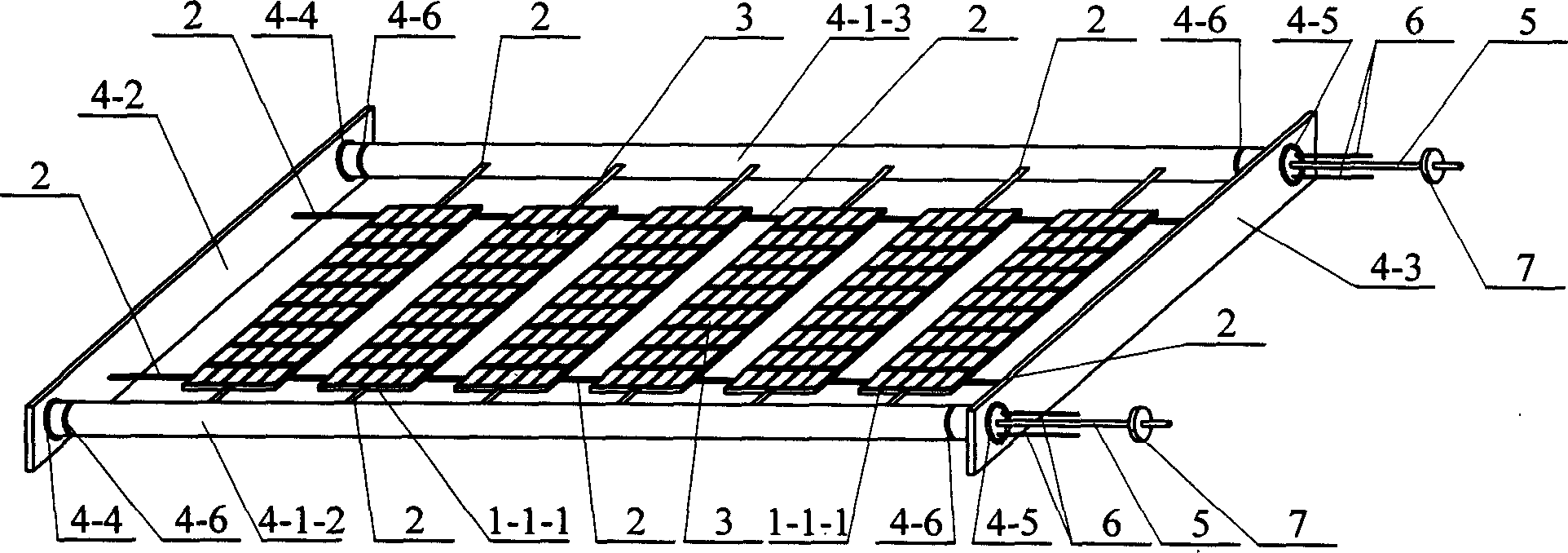
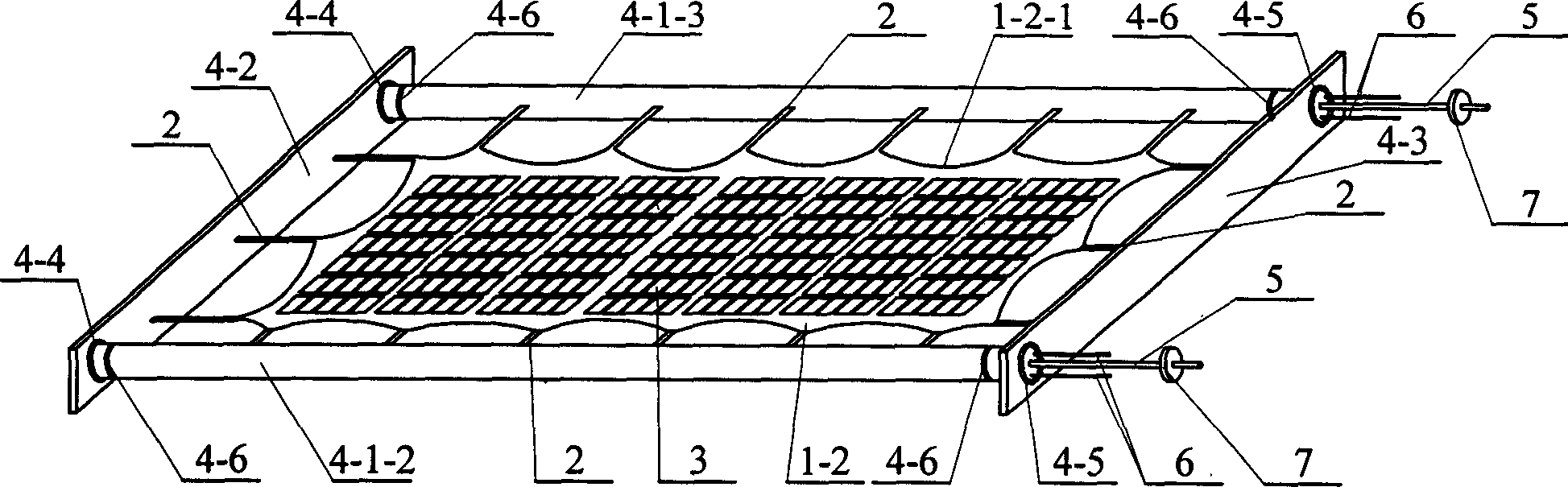
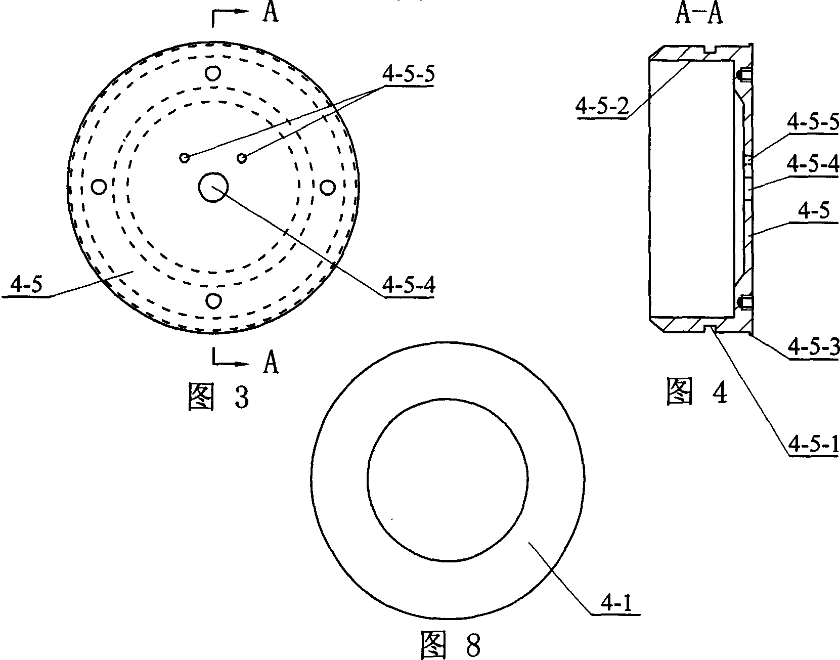
[0006] Specific implementation mode one: combine figure 1 , figure 2 , Figure 7, Figure 9 Describe this embodiment, this embodiment is made up of base plate, lace 2, patch layer 3, frame 4 that can be rigidized and inflated to expand, inflation pipeline 5, wire 6, control valve 7; Described frame 4 is equipped with along frame The substrate placed vertically, the substrate and the frame 4 are fixedly connected by a tie 2; the upper end of the substrate has a patch layer 3, and the left end of the wire 6 is installed on the support tube 4 on the frame 4, which can be rigidified and inflated -1 and is connected with the electric heating layer 4-1-1 of the support tube 4-1, the left end of the inflation pipeline 5 is installed in the support tube 4-1, and the control valve 7 is installed on the inflation pipeline 5; The substrate is a rigid substrate or a flexible substrate 1-2.

specific Embodiment approach 2

[0007] Specific implementation mode two: combination figure 1 , Figure 9 Describe this embodiment, the rigid substrate of this embodiment is composed of a group of rigid substrate units 1-1-1 placed in parallel, between two adjacent rigid substrate units 1-1-1 and the rigid substrate unit 1-1-1 It is fixedly connected with the frame 4 through a tether 2. The base plate is composed of a group of rigid base plate units 1-1-1, and this structure can keep the base plate flat and easy to fold. Other components and connections are the same as those in the first embodiment.

specific Embodiment approach 3

[0008] Specific implementation mode three: combination figure 2 , Figure 9 To illustrate this embodiment, the flexible substrate 1-2 of this embodiment is composed of at least one layer of polymer film or at least one layer of resin pre-impregnated fiber fabric, and the flexible substrate 1-2 is fixedly connected to the frame 4 through a tie 2 . The flexible substrate 1-2 has the advantages of simple structure, light weight, high folding efficiency and small folding volume. In this embodiment, in order to maintain the flatness of the flexible substrate 1-2, the outer periphery of the flexible substrate 1-2 is connected to the tether 2 in the form of a catenary 1-2-1. Other components and connections are the same as those in the first embodiment.


PUM


Abstract

This invention relates to rigidity and charging extension plane frame supportive structure, which solves the current solar sailboard and plane antenna plane frame supportive structure mechanic extension and complex existence structure and bad reliability and low efficiency of folding. The frame rack is loaded with frame rack longitude baseboard, wherein, the baseboard and frame rack is connected through band; the baseboard upper end has sticking layer; the wire left end is fixed on frame rack supportive tube and is connected to supportive tube with electricity layer; the charging channel left end is fixed inside supportive tube with control valve.

Description

technical field [0001] The present invention relates to a deployable planar frame support structure for use on planar antennas or solar panels. Background technique [0002] Planar antennas and solar panels have been widely used in aircraft such as satellites, manned spacecraft, and space stations. The key to the normal operation of planar antennas and solar panels is whether their planar frame support structures can be deployed normally. The expansion of the traditional planar frame support structure mainly adopts a mechanical rigid structure. This expansion support structure is composed of many rigid components connected by a connecting mechanism, a control expansion mechanism and a locking mechanism, so it has a complex structure and is prone to failure in use. , poor deployment reliability, heavy overall weight, and low folding efficiency, especially the above-mentioned problems that exist in the deployment support structure of large-scale solar panels and planar antenna...

Claims


Application Information

Patent Timeline
Patent Type & Authority Applications(China)
IPC IPC(8): H01Q1/12H02S20/00
CPCY02E10/50
Inventor 苗常青万志敏杜星文
Owner HARBIN INST OF TECH
Why Eureka
Try Eureka