Structure and preparation method of aluminum liquid-cooled chassis

A technology of liquid cooler and cooler, which is applied in the construction parts of electrical equipment, cooling/ventilation/heating modification, electrical components, etc. It can solve the problems of poor weldability, high processing cost, and solder accumulation, etc., to meet high power requirements. , excellent welding performance, and the effect of improving the production pass rate

Active Publication Date: 2018-09-25
CHENGDU SIWI HIGH TECH IND GARDEN
View PDF4 Cites 0 Cited by
  • Summary
  • Abstract
  • Description
  • Claims
  • Application Information

AI Technical Summary

Problems solved by technology

[0003] 3D printing technology belongs to the field of additive manufacturing, and it is limited and obvious in the field of meeting the needs of individualized design. Because metal 3D printing technology is not mature enough, the processing cost is huge, which is the limiting factor for the current promotion and application
The commonly used brazing filler metal is Al88SiMg brazing filler metal, which has excellent weldability to 3A21 aluminum with low strength, while the weldability of 6061 aluminum and 6063 aluminum with higher strength is poor
In addition, in order to realize the sealing of the flow channel of the cooling plate structure, the amount of solder is generally too much, and the welding process of the fine flow channel is easy to accumulate solder in the product, resulting in blockage of the flow channel

Method used


Image

  • Structure and preparation method of aluminum liquid-cooled chassis
  • Structure and preparation method of aluminum liquid-cooled chassis

Examples


Embodiment 1

[0025] A method for preparing an aluminum liquid-cooled chassis structure, comprising the following steps:

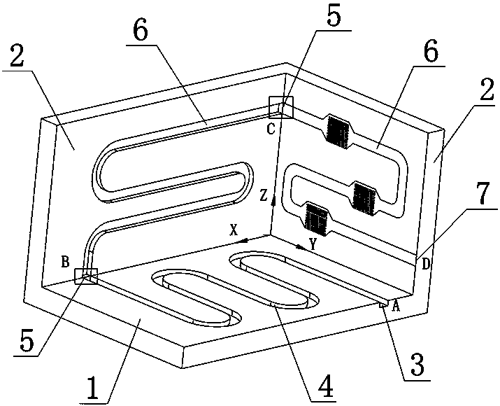
[0026] S1. Processing of cooling plate parts: According to the final structural size and welding allowance of cooling bottom plate 1 and cooling wall plate 2, determine the processing content of the parts, and shape them through mechanical processing. The flatness of the welding surface is less than 0.3mm, and the roughness level of the welding surface Higher than Ra1.6, the machining allowance of the cooling plate after welding is 3mm on one side;

[0027] S2. Cooling plate welding process: the cooling bottom plate 1 and the cooling wall plate 2 are respectively chemically cleaned to remove the surface oxide film, and a protective agent is used to prevent the secondary oxidation of the workpiece, and they are formed by vacuum diffusion welding. The welding temperature is 560 ° C. The pressure is 5MPa, and the sealing of the cooling plate flow channel is tested after we...

Embodiment 2

[0032] A method for preparing an aluminum liquid-cooled chassis structure, comprising the following steps:

[0033] S1. Processing of cooling plate parts: According to the final structural size and welding allowance of cooling bottom plate 1 and cooling wall plate 2, determine the processing content of the parts, and shape them through mechanical processing. The flatness of the welding surface is less than 0.3mm, and the roughness level of the welding surface Higher than Ra1.6, the machining allowance of cooling plate after welding is 2.5mm on one side;

[0034] S2. Cooling plate welding process: chemically clean the cooling bottom plate 1 and the cooling wall plate 2 to remove the surface oxide film, and use a protective agent to prevent the secondary oxidation of the workpiece. They are formed by vacuum diffusion welding. The welding temperature is 555°C. The pressure is 4MPa, and the sealing of the cooling plate flow channel is tested after welding;

[0035] S3. Secondary ...

Embodiment 3

[0039] A method for preparing an aluminum liquid-cooled chassis structure, comprising the following steps:

[0040]S1. Processing of cooling plate parts: According to the final structural size and welding allowance of cooling bottom plate 1 and cooling wall plate 2, determine the processing content of the parts, and shape them through mechanical processing. The flatness of the welding surface is less than 0.3mm, and the roughness level of the welding surface Higher than Ra1.6, the machining allowance of the cooling plate after welding is 2mm on one side;

[0041] S2. Cooling plate welding process: chemically clean the cooling bottom plate 1 and the cooling wall plate 2 to remove the surface oxide film, and use a protective agent to prevent the secondary oxidation of the workpiece. They are formed by vacuum diffusion welding. The welding temperature is 550°C. The pressure is 2MPa, and the sealing of the cooling plate flow channel is tested after welding;

[0042] S3. Secondary...


PUM


Abstract

The invention relates to an aluminum liquid cooling cabinet structure comprising a cooling bottom plate and a plurality of cooling wall plates. A plurality of cooling wall plates are vertically disposed on the edges of the cooling bottom plate to form a three-dimensional cavity. The edge part of the cooling bottom plate is provided with a cooling liquid inlet, and the upper surface of the cooling bottom plate is provided with a liquid cooling channel A. One end of the liquid cooling channel A is communicated with the cooling liquid inlet, and the inner side wall of every cooling wall plate is provided with a liquid cooling channel B, and in addition, one end of the liquid cooling channel B is connected with the other end of the liquid cooling channel A by a welded joint, and the other end of the liquid cooling channel B is communicated with one end of the adjacent liquid cooling channel B. The edge of one cooling wall plate is provided with a cooling liquid outlet, which is communicated with the last liquid cooling channel B. The invention also discloses the preparation method of the aluminum liquid cooling cabinet structure. A three-dimensional liquid cooling cabinet structure is changed from conventional two-dimensional heat dissipation to three-dimensional heat dissipation, and heat dissipation power is selected and controlled according to a heat dissipation requirement, and therefore high power and three-dimensional heat dissipation requirements of radio frequency products are satisfied.

Description

technical field [0001] The invention relates to the technical field of liquid-cooled cabinets, in particular to a structure and a preparation method of an aluminum liquid-cooled cabinet. Background technique [0002] The chassis is the carrier of electronic components such as radar radio frequency modules, high-voltage power supplies, and TR components, to meet the heat dissipation requirements of high-power electronic equipment during use. The traditional heat dissipation structure mainly includes three types: air-cooled chassis heat dissipation, air-cooled cooling plate and liquid-cooled cooling plate, and the heat dissipation structure is concentrated as a two-dimensional plane heat dissipation. With the development and large-scale application of radio frequency technology, the cooling power requirements of the chassis have increased significantly. [0003] 3D printing technology belongs to the field of additive manufacturing, and it is limited and obvious in the field o...

Claims


Application Information

Patent Timeline
Patent Type & Authority Patents(China)
IPC IPC(8): H05K7/20
CPCH05K7/20272
Inventor 敬小军彭勃王远荣崔建军
Owner CHENGDU SIWI HIGH TECH IND GARDEN
Why Eureka
Try Eureka